Operating Instructions Digital Video Cassette Recorder Model No. AJ- P Before operating this product, please read the instructions carefully and save this manual for future use.
IMPORTANT “Unauthorized recording of copyrighted television programs, video tapes and other materials may infringe the right of copyright owners and be contrary to copyright laws.” Operating precaution Operation near any appliance which generates strong magnetic fields may give rise to noise in the video and audio signals. If this should be the case, deal with the situation by, for instance, moving the source of the magnetic fields away from the unit before operation.
FCC Note: This equipment has been tested and found to comply with the limits for a class A digital device, pursuant to Part 15 of the FCC Rules. These limits are designed to provide reasonable protection against harmful interference when the equipment is operated in a commercial environment. This equipment generates, uses, and can radiate radio frequency energy and, if not installed and used in accordance with the instruction manual, may cause harmful interference to radio communications.
Contents Introduction . . . . . . . . . . . . . . . . . . . . . . . . . . . . . . . .4 Features . . . . . . . . . . . . . . . . . . . . . . . . . . . . . . . . . . .5 Parts and their functions . . . . . . . . . . . . . . . . . . . . .7 Front panel . . . . . . . . . . . . . . . . . . . . . . . . . . . . . . .7 Display panel . . . . . . . . . . . . . . . . . . . . . . . . . . . . .16 Rear panel . . . . . . . . . . . . . . . . . . . . . . . . . . . . . . .18 Connections . . . . . . . . . . . . . . . . . . . .
Features Light and compact This unit is a 4U size digital VTR and can be easily mounted in a 19-inch rack by using the rack mounting adapters (AJ-MA75P, optional accessory). Up to 126 minutes of recording at the 50 Mbps rate The cassette tapes used have 1/4-inch width to achieve a compact design. M cassette (when AJ-P66MP is used) 50 Mbps: Max. 33 minutes 25 Mbps: Max. 66 minutes L cassette (when AJ-5P92LP is used) 50 Mbps: Max. 92 minutes 25 Mbps: Max.
Features (continued) Multifunctional interface O Serial digital input/output A component serial interface is provided as standard and enables interfacing of the serial digital component signals. O Analog video input/output Both composite and component signal outputs are provided as standard. Use of an analog video input board (AJ-YA931G, optional accessory) enables interfacing of the component (Y, PB, PR) and composite signal input.
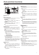
Parts and their functions Front panel 1 2 8 9 EJECT DVCPRO 50 ON POWER XL/L/M-cassette 2X DVCPRO REMOTE SUPER REC INH DV OFF TCG MODE ON ON INT TAPE OFF OFF EXT EE COUNTER ASSEM VIDEO CUE TC RESET INSERT CH 1 CH 2 CH 3 CH 4 PF 2 PF 3 PF 4 SEARCH SHTL SLOW PUSH PF 1 STAND BY PLAYER RECORDER TC PRESET METER INPUT SELECT FULL/FINE VIDEO AUDIO HEADPHONES AUDIO MIX 1&2 AUTO EDIT PREROLL A IN CH1/3 CH2/4 REC CH2/4 SET MENU PF EDIT PLAY REC REW STOP FF A OU
Parts and their functions (continued) Front panel = FF button When this button is pressed, the tape is fast forwarded. The fast forwarding speed can be selected using setup menu No.102 (FF. REW MAX).
Parts and their functions (continued) Front panel FA B EC EJECT DVCPRO 50 ON POWER XL/L/M-cassette 2X DVCPRO REMOTE SUPER REC INH DV OFF TCG MODE ON ON INT TAPE OFF OFF EXT EE COUNTER ASSEM VIDEO CUE TC RESET INSERT CH 1 CH 2 CH 3 CH 4 PF 2 PF 3 PF 4 SEARCH SHTL SLOW PUSH PF 1 STAND BY PLAYER RECORDER TC PRESET METER INPUT SELECT FULL/FINE VIDEO AUDIO HEADPHONES AUDIO MIX 1&2 AUTO EDIT PREROLL A IN CH1/3 CH2/4 REC CH2/4 SET MENU PF EDIT PLAY REC REW STOP
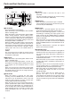
Parts and their functions (continued) Front panel H ASSEM button This button is pressed to proceed with assemble editing. It has a self-illuminating lamp which comes ON when the button is pressed and goes OFF when it is pressed again. I INSERT buttons The input signals to be edited when insert editing is to be conducted are selected by pressing one of these seven buttons. Each of these buttons has a self-illuminating lamp which comes ON when the button is pressed and goes OFF when it is pressed again.
Parts and their functions (continued) Front panel P 3.5-inch color LCD monitor This monitor enables the output images and menu settings to be monitored. Information such as the time code is not displayed. [Saving function of LCD monitor] If none of the controls on the front panel are operated or the cassette tape does not move at all for about 5 minutes, the saving function is activated, and the display vanishes from the LCD monitor.
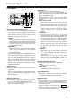
Parts and their functions (continued) Front panel T REC CH1/CH3 and REC CH2/CH4 buttons, and S CH1/3 and CH2/4 lamps These buttons are used to switch the input signals to be recorded on the CH1, CH2, CH3 and CH4 audio channels in conjunction with the AUDIO MIX switch S.
Parts and their functions (continued) Front panel VU X AUDIO VOL SEL (REC/PB) switch This switches the function of the audio level control knobs W between recording and playback.
Parts and their functions (continued) Front panel _ SET UP (BLK) control and switch EJECT DVCPRO 50 ON POWER 2X XL/L/M-cassette DVCPRO DV SUPER REC INH REMOTE OFF TCG MODE ON ON INT TAPE OFF OFF EXT EE COUNTER ASSEM VIDEO CUE TC RESET INSERT CH 1 CH 2 CH 3 CH 4 PF 1 PF 2 PF 3 PF 4 SEARCH SHTL SLOW PUSH STAND BY PLAYER RECORDER TC PRESET METER INPUT SELECT FULL/FINE VIDEO AUDIO HEADPHONES AUDIO MIX 1&2 AUTO EDIT PREROLL A IN CH1/3 CH2/4 REC CH2/4 SET MENU PF ED
Parts and their functions (continued) Front panel PF EJECT DVCPRO 50 ON POWER 2X XL/L/M-cassette DVCPRO DV SUPER REC INH REMOTE OFF TCG MODE ON ON INT TAPE OFF OFF EXT EE ASSEM RESET INSERT CH 1 VIDEO CUE TC SEARCH SHTL + SLOW PUSH PF 1 METER INPUT SELECT FULL/FINE VIDEO AUDIO HEADPHONES AUDIO MIX 1&2 PREVIEW/ REVIEW AUTO EDIT PREROLL A IN CH 2 CH 3 CH 4 PF 2 PF 3 PF 4 STAND BY PLAYER RECORDER SET TC PRESET PF MENU EDIT PLAY REC REW STOP FF JOG PF A OU
Parts and their functions (continued) Display panel 1 525 2 625 3 WIDE 4 REMOTE dB 0 VIDEO AUDIO Y PB PR CMPST ANALOG AES/EBU USER SET SDI SDTI/1394 SG -4 -8 -12 -16 6 5 SDI SDTI/1394 SG 1 2 87 9 SCH SERVO U = EDIT REC INH DVCPRO 50 DVCAM -20 -25 -30 - CTL TC UB 1 TV system displays The selected TV system is displayed here. It is possible to switch between the 525 interlace and 625 interlace systems by setting setup menu item No. 070 (TV SYSTEM).
: EDIT, EDIT REC, REC and REC INH lamps EDIT: This lights when an editing mode has been selected. EDIT REC: This lights when the edit recording mode has been established. REC: This lights when the recording mode has been established. REC INH: This lights in the recording inhibit status (when the REC INH switch at the bottom front panel is set to ON or the cassette is in the accidental erasure prevention status). In this status, recording and editing are not possible.
Parts and their functions (continued) Rear panel 1 2 3 45 6 7 AES/EBU AC IN REMOTE ANALOG CH1/2 IN 8 9: ; ANALOG VIDEO IN SDI REMOTE IN/OUT ON Y CH1 PUSH AUDIO PUSH CH2 IN PUSH TC IN OUT IN 75Ω CH3/4 IN 1 OFF REMOTE CH3 PUSH PB CH1/2 OUT REF VIDEO IN PUSH CH4 TC OUT CH2 MON L ACTIVE THROUGH 2 ENCODER REMOTE ON PR CH3/4 OUT OUT 75Ω OPTION 3 OFF CH1 RS-232C AUDIO OUT (SUPER) OPTION Y 1 PB (WFM) PR (SUPER) VIDEO OUT PARALLEL CH3 2 CH4 MON R 3 SIGNAL GND
Parts and their functions (continued) Rear panel A PARALLEL REMOTE connector This connector is used when the VTR is to be operated by an external component. B ANALOG AUDIO OUT connectors The analog audio signals are output through these connectors. < Fan This fan is used to cool down the VTR. If, for any reason, the fan stops, “E-10” will appear on the counter display. = SIGNAL GND terminal This is connected to the signal ground terminal on the component connected to this VTR in order to minimize noise.
Connections Source machine: Set the REMOTE button 3 on the front panel to the remote mode (REMOTE lamp ON). Recorder: Set the REMOTE button 3 on the front panel to the local mode (REMOTE lamp OFF).
Connections (continued) Connections with editing controller EJECT DVCPRO 50 ON POWER 2X XL/L/M-cassette DVCPRO DV SUPER REC INH REMOTE OFF TCG MODE ON ON INT TAPE OFF OFF EXT EE COUNTER ASSEM VIDEO CUE TC RESET INSERT CH 1 CH 2 CH 3 CH 4 PF 1 PF 2 PF 3 PF 4 SEARCH SHTL SLOW PUSH STAND BY PLAYER RECORDER TC PRESET METER INPUT SELECT FULL/FINE VIDEO AUDIO HEADPHONES AUDIO MIX 1&2 AUTO EDIT PREROLL A IN CH1/3 CH2/4 REC CH2/4 SET MENU PF EDIT PLAY REC REW STOP
Tapes Consumer-use DV and DVCAM cassettes (Standard DV and DVCAM cassettes, mini DV and DVCAM cassettes) O Use a cassette adapter (AJ-CS455P) when a mini DV or DVCAM cassette is to be used. Note that inserting a mini DV or DVCAM cassette without the use of a cassette adapter will cause malfunctioning. Also note that long-duration mini DV cassettes (80 minutes in the standard mode and 120 minutes in the LP mode) cannot be used. O It is not possible to play back tapes which have been recorded in the LP mode.
Jog/Shuttle Jog mode Shuttle mode the search dial so that it remains pressed in. 1 Press Check that the JOG lamp has lit. the search dial so that it is released from the 1 Press pressed-in position. the search dial. 2 Turn The dial’s click-stops are released, and the tape is played back at the speed (–1a to +1a) corresponding to the speed at which the dial is turned. The maximum speed can be switched using setup menu No. 323 (JOG FWD MAX) and No. 324 (JOG REV MAX) settings.
Manual editing the editing mode. 1 Select ASSEMBLE: Assemble (frame-to-frame continuity) editing is performed in this mode. INSERT: Insert editing is performed in this mode. the channels to be edited. 2 Select For insert editing, press the buttons corresponding to the channels to be edited so that their lamps light. monitoring the TV monitor, search the 4 While position (IN point) where the editing is to be started, and press the PLAY and EDIT buttons together at this position.
Automatic editing (deck-to-deck) Switch settings and adjustments When using the AJ-SD965 as the recorder When using the AJ-SD965 as the player 1 Set the POWER switch to ON. 1 Set the POWER switch to ON. the INPUT SELECT buttons to select the video the AUDIO VOL SEL (REC/PB) switch to the 2 Use 2 Set and audio input signals. PB position. 3 Switch the time counter display to TC, CTL or UB.
Automatic editing (deck-to-deck) (continued) Selecting the editing mode Registering the edit points the editing mode. 1 Select For assemble editing, press the ASSEM button. the edit IN point by performing the jog or 1 Locate shuttle operation. For insert editing, press the INSERT button. ASSEM: This sets the unit to assemble (frame-to-frame continuity) editing mode. INSERT: This sets the unit to insert editing mode. the channels to be edited. 2 Select With assemble editing, the ASSEM lamp lights.
Automatic editing (deck-to-deck) (continued) Checking and previewing edit points the IN (or OUT) button to check the edit 1 Press point. The value of the registered edit point appears EJECT DVCPRO 50 ON POWER 2X XL/L/M-cassette DVCPRO DV on the display panel.
Automatic editing (deck-to-deck) (continued) Modifying edit points an edit point 1 Re-registering Locate the new edit point by performing the jog or shuttle operation, and press the IN (or OUT) button and SET button at the same time to re-register the edit point. an edit point in 1-frame increments 2 Modifying (trimming function) Press the TRIM button while holding down the IN (or OUT) button. Each time the + button is pressed, the point is moved ahead by one frame.
Automatic editing (deck-to-deck) (continued) Executing and reviewing automatic editing the AUTO EDIT button. 1 Press Automatic editing is now executed. completion of the editing, press the REVIEW 2 Upon button. O To suspend editing at any time, press the STOP button. O When the edit OUT point is reached, the tape is post-rolled, after which it stops.
Audio split editing The video edit points and audio edit points can be registered independently, and editing can be executed with the video point offset from the audio points. Audio edit points cannot be registered when the assemble editing mode has been selected. After registering the edit points, proceed with the same operations as for insert editing.
Audio split editing (continued) $ Duration display The duration can be indicated on the display panel only. Between the video IN and OUT points: Press the IN button and OUT button at the same time. Between the audio IN and OUT points: Press the A IN button and A OUT button at the same time.
Variable memory editing Using the unit as a controller (deck-to-deck editing mode recorder) to control the playback speed of the VTR used as the player, editing can be performed in speed variable mode. $ Selecting the variable memory mode When deck-to-deck editing (either the RECORDER or PLAYER lamp lights) is to be performed, set the initial speed (–1.0 to +2.0) by turning the search dial with the SET button held down to transfer the unit to variable memory mode.
PF (Programmable Function) functions Four most frequently used setup items can be registered in the four PF buttons. Registering setup items in the PF buttons the search dial to move the cursor (2) to the 4 Turn item to be registered. the STOP button. 5 Press The display screen returns to the status in step 2, and the registered item is displayed at the position of the specified PF button. register the next item in the next PF button, 6 To repeat steps 2 to 5.
Setup (initial settings) This VTR’s main settings are performed while making selections using a system of menus. FF button button. The settings on the menu screen and display now flash. When the dial is turned clockwise, the setting number is incremented; conversely, when it is turned counterclockwise, it is decremented. O At this time, when the RESET button is pressed while holding down the search button, the setting value is returned to the factory setting.
Setup menus This VTR can hold five user files, each of which has its own specific menu settings, and one of these files can be selected for use. Changing the file 1 Press the MENU (SHIFT+RECORDER). the FF button is pressed while holding down 2 When the SHIFT button, the next user file is selected; conversely, when the REW button is pressed while holding down the SHIFT button, the previous user file is selected.
Setup menus (continued) Loading user files The contents of the USER2, USER3, USER4 or USER5 file can be copied (loaded) into the USER1 file. Also, the contents of the USER1 file can be copied (saved) into the USER2, USER3, USER4 or USER5 file. USER 2 Lock mode can be set USER 3 Lock mode can be set USER 4 Lock mode can be set USER 5 Lock mode can be set Load/save Load/save Load/save 1 Press the MENU screen and counter display. Menu screen SETUP-MENU Load/save USER 1 the SET button.
Setup menus (continued) Saving user files 1 Press the MENU the PLAY button. 6 Press The settings of USER1 are saved in the user file (SHIFT+RECORDER). the REW button or FF button while holding 2 Press down the SHIFT button to select the USER1 file. the search dial to move the cursor (2) on the 3 Turn menu screen to No. A01 (SAVE). SETUP-MENU MENU NO.A00-0000 804 BLANK LINE BLANK A00 LOAD USER2 USER2 2A01 SAVE A02 P.ON LOAD OFF END selected in step 4 and stored in the memory.
Setup menus (continued) SYSTEM menu No./Item 00 Description This selects the signal to output from the VIDEO OUT 2 connector. WFM SEL No./Item 14 SCH COARSE 0000 0001 CTL : The CTL signal is output. TC : The TIME CODE signal is output. 0002 VIDEO : The VIDEO OUT signal is output. 0003 RF_L : The PB L RF signal is output. 0004 RF_R : The PB R RF signal is output. 0005 ENV_L : The PB L ENV signal is output. 0006 ENV_R : The PB R ENV signal is output.
Setup menus (continued) SYSTEM menu No./Item Description No./Item 18 System phase adjustment. 30 SYS H OFFSET 0000 –3 : –13.4 µsec 0001 –2 : –8.96 µsec 0002 –1 : –4.52 µsec 0003 0 : 0 sec 0004 1 : +4.52 µsec 0005 2 : +8.96 µsec 0006 3 : +13.4 µsec Factory settings will remain unchanged even if an attempt is BRIGHT 19 SYS SC/H This sets whether the system phase is to be adjusted by the unit or from the external encoder remote controller.
Setup menus (continued) USER menu No./Item 000 P-ROLL TIME This sets the preroll time. The preroll time can be set from 0 to 15 seconds in 1-second increments. 0000 : 0005 : 0015 001 LOCAL ENA No./Item Description 0s : 5s : 15s When the automatic mode [PREVIEW, EDIT] is set, the unit operate if the preroll set to 0 seconds. This selects the buttons on the front panel which can be operated when the REMOTE button is set to the remote mode (REMOTE lamp ON).
Setup menus (continued) USER menu No./Item 009 CHARA H-POS This sets the position of the characters on the horizontal plane for the time code and other super displays output to the VIDEO OUT 3/SDI OUT 3 connector. 0000 : 0004 : 0016 010 CHARA V-POS CHARA TYPE 0001 This sets the VTR’s recording and playback format. This sets the format in which the tape is to be played back. 0000 MANUAL : The format complies with the setting of setup menu No.
Setup menus (continued) USER menu No./Item 100 SEARCH ENA 101 Description This selects the direct search dial operation. 0000 DIAL : For direct search dial operations. 0001 KEY : Operation is not transferred to the search mode unless the search button is pressed. No./Item 105 AUTO EE SEL SHTL MAX 102 a8.4 : 8.4a normal speed a16 : 16a normal speed a32 : 32a normal speed This sets the maximum speed for FF and REW operations. FF.
Setup menus (continued) USER menu No./Item 109 AUTO REW This selects whether to rewind the tape automatically to the tape start when the tape end is detected. 0000 0001 110 No./Item Description 111 FRZ MODE SEL OFF : The tape stops at the tape end. ON : The tape is rewound to the tape start. 0000 OFF : The VTR does not stop. 0001 ON : The VTR stops automatically.
Setup menus (continued) USER menu No./Item Description 114 This selects whether to cause the REC INH lamp to flash or light up when the cassette REC INH LAMP has been set to the accidental erasure prevention status. 0000 LIGHT : The lamp lights up. 0001 FLASH : The lamp flashes. When the REC INH switch is set to ON, the REC INH lamp always lights regardless of the general setting status.
Setup menus (continued) USER menu No./Item 200 No./Item Description This selects whether two or more VTRs are to be operated in synchronization. PARA RUN 208 9P SEL 0000 NON : Parity bit is not used. 0001 ODD: An odd number of bits is used for the parity system. 0002 EVEN: An even number of bits is used for the parity system. This selects whether the 9P connector is to function when the REMOTE button is set to the remote mode (REMOTE lamp ON).
Setup menus (continued) USER menu No./Item 301 IN/OUT DEL Description This selects the operation to be performed when an edit point has been set incorrectly (when the OUT point is before the IN point). No./Item 305 EDIT RPLCE1 0000 MANU : Editing is not executed unless the illegal edit point is cleared or set again properly. 0001 AUTO : The edit points already input are automatically cleared. 303 STD/ NON-STD 304 SERVO REF The underlined items indicates the initial setting.
Setup menus (continued) USER menu No./Item 308 EDIT RPLCE4 The same type of setting as setup menu No. 305. This selects the channel concerned when the CH4 edit preset is set in compliance with the ON or OFF presetting for the analog audio signals designated by the controller. 0000 N-DEF : Not set. 0001 CH1 : Compliance with analog CH1 edit preset. 0002 CH2 : Compliance with analog CH2 edit preset. 0003 CH1+2 : Compliance with analog CH1 or CH2 edit preset.
Setup menus (continued) USER menu No./Item No./Item Description 324 This sets the maximum JOG REV speed. JOG REV MAX 0000 –4.1 : –4.1 (–3.1)a speed 0001 –1.85 : –1.85a speed 0002 –1 : –1a speed 0003 –0.43 : –0.43 (–0.5)a speed OThe value for the DV/DVCAM tape is shown in parenthesis ( ). OThe maximum speed is set to –1a when the dial on the front panel is operated. 401 When the time selected as the setup menu item No.
Setup menus (continued) USER menu No./Item 500 VITC BLANK
Setup menus (continued) USER menu No./Item 511 VITC OUT
Setup menus (continued) USER menu
Setup menus (continued) USER menu No./Item 620 ESR MODE
Setup menus (continued) USER menu No./Item 623 SETUP 50
Setup menus (continued) USER menu No./Item 660
Setup menus (continued) USER menu
Setup menus (continued) USER menu
Setup menus (continued) USER menu
Setup menus (continued) USER menu No./Item 800 Description For selecting the mode for recording signals on additional lines. ADD LINE 25 0000 OFF : No signals are recorded on additional lines. 0001 YC422 : The 422 mode signals are recorded on 1 line. 0002 YC411 : The 411 mode signals are recorded on 1 line. 0003 Y1_B/W : Only the Y signal is recorded on 1 line directly. 0004 Y1_BPF : Only the Y signal is recorded on 1 line after it has been separated from the C signal.
Setup menus (continued) USER menu No./Item 801 Description For selecting the mode for recording signals on additional lines. ADD LINE 50 0000 OFF : No signals are recorded on additional lines. 0001 YC422 : The 422 mode signals are recorded on 2 lines. 0002 Y4_B/W : Only the Y signal is recorded on 4 lines directly. 0003 Y4_BPF : Only the Y signal is recorded on 4 lines after it has been separated from the C signal. 0004 C4 : Only the C signal is recorded on 4 lines.
Setup menus (continued) USER menu No./Item 803 TELETEXT DET Description For selecting the method used to detect the lines in which the teletext signals are to be recorded. 0000 OFF : The teletext signals are not recorded. 0001 AUTO : The teletext signals are automatically detected and recorded. 0002 MANU : The lines in which the teletext signals are to be recorded are selected and set.
Setup menus (continued) USER menu No./Item 900 Description No./Item This sets the LCD monitor’s saving function (see page 11). LCD PROTECT A02 P. ON LOAD 0000 OFF : The saving function is not established. 0001 ON : The saving function is established. 901 BL BRIGHT 0000 NORMAL : The backlight lights at the normal brightness. 0001 HIGH : The backlight lights more brightly than normal.
Time code/user bit Time code The time code is used when the time code signal generated by the time code generator (time code signal generator) is to be recorded on the tape, its values are to be read by the time code reader (time code signal reader), and the absolute position of the tape is to be displayed in increments of hours, minutes, seconds and frames. The time code is written in the sub-code area (data area) of the helical track.
Time code/user bit (continued) Setting the external time code Reproducing the time code/user bit 1 Set the VTR to stop mode. 1 Set the VTR to stop mode. 2 Select “TC” using the COUNTER button. 2 Select “TC” or “UB” using the COUNTER button. the TCG switch to EXT. (External time code the PLAY button. 3 Set 3 Press selection) Playback starts and the time code is shown on the following settings can be selected with setup 4 The menu No. 505 (EXT TC SEL).
Superimpose screen The control signals, time code, etc. are displayed using abbreviations. TV monitor Characters displayed The background of characters superimposed on the display can be changed using setup menu No. 011 (CHARA TYPE). TCR 22 : 22 : 22 : 22 TCR 22 : 22 : 22 : 22 Abbreviations: TV monitor TCR 2 2 : 2 2 : 2 2 : 2 2 TV monitor CTL : Control signal count value TCR : Time code data recorded in the SBC area TCR.
Video output signals and servo reference signal This section explains how the output signals and servo reference signal are selected. External synchronization of video output signals The video output signals are output in synchronization with the REF VIDEO input signal or video input signal. As shown in the figure below, this signal is selected in accordance with the setup menu settings, VTR mode and availability of the video input signal.
Video output signals and servo reference signal (continued) Servo reference signal The REF VIDEO input signal or video input signal is selected as the servo reference signal. As shown in the figure below, the signal is selected in accordance with the setup menu settings, VTR mode and availability of the video input signal. Synchronization is determined as follows depending on the availability of the REF VIDEO input signal when “BB”, “CB100” or “CB75” has been selected as the setup menu No.
Audio V fade function When editing tapes, the edit point splicing selection (setup menu No. 311 and 312) information is recorded on the tape. This information is then sensed during playback, and V fade or cut processing is automatically performed for these sections. However, only when the playback fade selection (No. 727) is AUTO. When the edit point splicing selection (setup menu No. 311 and 312) is CUT Audio signal A Audio signal B Noise appears at the edit splice.
Audio recording channel and monitor output selection Audio recording channel Monitor output channel The audio recording channels are selected on the AUDIO setup menu as shown below. The monitor output channels are selected using the AUDIO MON SEL (L and R) and AUDIO MON SEL (MIX) buttons as shown below.
Rack mounting The unit can be mounted into a 19-inch standard rack using the optional rack-mounting adaptors (AJMA75P). For the installation rails, it is recommended that the 18-inch rail and bracket (model number CC3061-99-0400) by Chassis Trak be used. (The complete slide rail and bracket unit is not available from Panasonic.) For further details, consult your dealer. the AJ-MA75P rack mount adapter using the 4 Attach same 4 screws. the inner members of the slide rails.
Video head cleaning This unit is equipped with an auto head cleaning function which automatically reduces the amount of dirt on the video heads. However, in order to maximize the unit’s reliability, it is recommended that the video heads be cleaned as and when appropriate. For further details on how to actually clean the heads, consult with one of our service companies or with your dealer.
Error messages When a warning occurs in this unit, the error number is indicated on the counter display. Open the DIAG menu to display a description of the error on the counter display or monitor TV. When a operational malfunction has occurred in the unit, the error number flashes on the counter display. DIAG menu $ “WARNING” information display O A warning message is displayed whenever a warning occurs. When warnings have not been detected, “NO WARNING” is displayed.
Error messages (continued) $ Displaying the “HOURS METER” information Turn the search dial to move the cursor (2). The description for the item where the cursor is located is shown on the counter display. No./Item Ser Description Displays the unit’s serial No. If “T&S&M” is selected in the setup menu No. 008 (DISPLAY SEL), a message appears in the mode display whenever a warning or error occurs. When multiple events occur, the event with the highest priority is displayed.
Error messages (continued) Warning messages Priority High OMonitor display ODescription OVTR operation and corrective action E-10 (FAN STOP) This is displayed when the fan motor stops. VTR: Operation continues. OCheck that nothing is obstructing the fan movement. E-09 (NO RF) This appears during playback when a blank section (tape blank) lasting for one or more seconds has been detected. Such a section is identified as a tape blank when all of the following conditions are met.
Error messages (continued) Error messages Display E-20 DEW E-29 FRONT LOAD MOTOR E-31 LOADING MOTOR E-35 SERVO CONTROL ERROR E-37 SERVO COMM ERROR E-38 SERVO FG ERROR 74 ODescription OVTR operation and corrective action Display If condensation is detected, the error number flashes and the unit transfers to eject mode. The drum rotates after the cassette is ejected to eliminate the condensation.
Error messages (continued) Error messages Display E-64 S REEL ROTA TOO FAST E-67 T REEL ROTA TOO FAST E-69 T REEL TORQUE ERR E-70 S REEL TORQUE ERR E-71 CAP TENSION ERROR ODescription OVTR operation and corrective action Consult your dealer if the error message is still displayed even after restarting the unit. If the supply reel motor speed is abnormally high, the error number flashes on the display. VTR: STOP OSet the POWER switch to OFF and then to ON again.
RS-232C interface The VTR can be operated by commands when the RS232C interface is used. (See command table on pages 79, 80.) $ Conditions for acknowledging commands from RS-232C interface O The REMOTE button on the front panel must be set to the remote mode (REMOTE lamp ON). O The setup menu No. 204 “RS232C SEL” must be ON. If the above conditions are not met, [ACK] + [STX] ER001 [EXT] is returned to the external unit.
RS-232C interface (continued) Software specifications (Protocol) 1. Communication parameters Communication system Asynchronous, full duplex Communication speed 300/600/1200/2400/4800/9600 Bit length 7bit/8 bit Stop bit 1 bit/2 bit Parity bit NONE/ODD/EVEN ACK code ACK code returned/ACK code not returned The ACK code is what is returned from the VTR to the controller when data has been successfully sent from the controller.
RS-232C interface (continued) 3. Return format [VTR 5 controller (PC)] 4. Error code table The following responses are made to the command. If necessary, more than one response is made. $ When the communication has terminated normally 1. The receive completion message is returned. [ACK] 06h 2. The execution completion message is returned. [STX] [command] [data] [ETX] 02h XX XX XX XX.....XX 03h [command] : This is the message (data) which is returned or the execution completion message identifier.
RS-232C interface (continued) 5. Command table VTR operation $ Commands relating to operation control SHTL FORWARD O As for the return (completion) message, [ACK] is first returned when data is received, and the execution message is subsequently returned. It is only the execution message which is listed in this table. O In the case of commands not listed in the table, ER001 (invalid command) is returned after [ACK] has been returned.
RS-232C interface (continued) $ Commands relating to inquiries O As for the return (completion) message, [ACK] is first returned when data is received, and the execution message is subsequently returned. It is only the execution message which is listed in this table. O In the case of commands not listed in the table, ER001 (invalid command) is returned after [ACK] has been returned.
Connector signals VIDEO IN RS-422A REMOTE (9P) SDI IN (DIGITAL) BNCa2, Active through Y, PB, PR (ANALOG) BNCa3 (Board, option) VIDEO IN BNCa2, Loop-through, 75Ω termination switch provided (Board, option) REF VIDEO IN BNCa2, Loop-through, 75Ω termination switch provided VIDEO OUT SDI OUT (DIGITAL) BNCa3 Y, PB, PR (ANALOG) BNCa3 VIDEO OUT BNCa3 O REMOTE IN/OUT Pin No.
Connector signals (continued) PARALLEL REMOTE (25P) RS-232C D-SUB 25-pin (crossover cable supported) Pin No.
Specifications [GENERAL] Power supply: AC 100 – 240 V, 50/60 Hz Power consumption: 115 W 130 W (with all options) indicates safety information. Operating ambient temperature: 5°C to 40°C Operating ambient humidity: 10% to 80% (no condensation) Weight: 38.5 lb (17.5 kg) Dimensions (WaHaD): 16 3/4 inchesa6 15/16 inchesa16 7/16 inches (424 mma175.
Specifications (continued) [VIDEO] [AUDIO] $ Video output connector $ Audio input connector Analog component output: BNCa3 (Y, PB, PR) Y: 1.0 V [p-p], PB/PR: 0.486/0.7 V [p-p] switchable, (75% color bar, 7.5% setup) Analog composite output: BNCa3, video 1, video 2 (video/WFM selectable), video 3 (superimpose on/off) SDI output: BNCa3, SDI 1, SDI 2, SDI 3 (superimpose on/off), complies with SMPTE259M-C/ITU-R BT.
Memo
PANASONIC BROADCAST & TELEVISION SYSTEMS COMPANY UNIT COMPANY OF MATSUSHITA ELECTRIC CORPORATION OF AMERICA Executive Office: One Panasonic Way 4E-7, Secaucus, NJ 07094 (201) 348-7000 EASTERN ZONE: One Panasonic Way 4E-7, Secaucus, NJ 07094 (201) 348-7621 Southeast Region: 1225 Northbrook Parkway, Ste 1-160, Suwanee, GA 30024 (770) 338-6835 Central Region: 1707 N Randall Road E1-C-1, Elgin, IL 60123 (847) 468-5200 WESTERN ZONE: 3330 Cahuenga Blvd W.