Camera/VTR Operating Instructions Model No. AJ- E Model No. AJ- E Before operating this product, please read the instructions carefully and save this manual for future use.
$ DO NOT REMOVE UNSCREWING. PANEL COVER BY To reduce the risk of electric shock, do not remove cover. No user serviceable parts inside. Refer servicing to qualified service personnel. CAUTION: TO REDUCE THE RISK OF FIRE OR SHOCK HAZARD, REFER MOUNTING OF THE OPTIONAL INTERFACE BOARD TO AUTHORIZED SERVICE PERSONNEL.
Attention/Attentie OBatteries are used for the main power source and memory back-up in the product. At the end of their useful life, you should not throw them away. Instead, hand them in as small chemical waste. OVoor de primaire voeding en het reservegeheugen van het apparaat wordt gebruikgemaakt van een batterij. Wanneer de batterij is uitgeput, mag u deze niet gewoon weggooien, maar dient u deze als klein chemisch afval weg te doen.
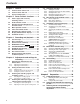
Contents Chapter 1 1-1 1-2 1-3 Features of the camera unit ...................... 6 Features of the VTR unit ........................... 7 System configuration ................................ 8 Chapter 2 2-1 2-2 2-3 2-4 2-5 2-6 2-7 2-8 Shutter modes ............................................. 30 Setting the shutter mode and speed ........... 30 Setting the synchro scan mode ................... 31 Selecting the recording signals and recording system .....................................
Contents 5-4 Audio input signal preparations ............. 67 5-4-1 5-4-2 5-4-3 5-4-4 7-3-11 7-3-12 When using the front microphone ............... 67 When using an external microphone ........... 67 When using a wireless receiver ................... 68 When using an audio component ................ 68 7-4 Mounting the unit on a tripod ................. 69 Attaching the shoulder strap .................. 69 Adjusting the position of the shoulder pad ..................................
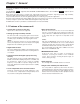
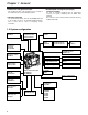
Chapter 1 General The models AJ-SDC615 and AJ-SDC905 are camera recorders featuring three CCD image sensors which each have a 2/3-inch on-chip lens. The AJ-SDC905 SDC905 supports both the DVCPRO and DVCPRO50 formats. (The AJ-SDC615 SDC615 supports only the DVCPRO format.) Both camera recorders feature a compact size, light weight, low power consumption, high image quality, high sensitivity, excellent mobility and outstanding dust-proof and moisture-proof characteristics.
Chapter 1 General 1-2 Features of the VTR unit ≥ DVCPRO and DVCPRO50 formats supported SDC905 The VTR unit compresses the images using a component digital recording system that uses the latest compression technology, and for the sound it employs non-compression PCM recording with an excellent signal-to-noise ratio, frequency band, waveform characteristics and reproduction characteristics of the finely detailed areas.
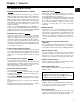
Chapter 1 General ≥ Built-in time code generator/reader This enables the time code information to be recorded on the dedicated sub-code track and played back. ≥ Metadata supported The unit allows information from the AJ-GPS900G GPS unit to be recorded on tape as the metadata UMID information. This is useful when it comes to managing on-tape information.
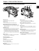
Chapter 2 Parts and their functions 2-1 Power supply and accessory mounting section 5 7 6 2 6 2 9 8 : 1 4 3 > 1 POWER switch This switch turns the power ON and OFF. 2 Battery mount This is for attaching the Anton Bauer battery pack. 3 DC IN (external power input) socket (XLR, 4-pin) When operating this unit using an AC power source, this socket is connected to the model AJ-B75 AC adapter (optional accessory).
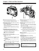
Chapter 2 Parts and their functions 2-2 Audio function section (input system) =<> ; : 3 7 2 6 8 ? 1 4 ? @ 59 1 MIC IN (microphone input) jack (XLR, 3-pin) Connect the microphone (optional accessory) here. The power for the microphone is supplied from this jack. 5 AUDIO IN CH1/CH2 (audio input channel 1 & 2) connectors (XLR, 3-pin) An audio component or microphones are connected here.
Chapter 2 Parts and their functions 2-2 Audio function section (output system) 9 AUDIO OUT connector (XLR, 5-pin) The audio signals recorded on audio channels 1 and 2 or audio channels 3 and 4 are output from this connector. With the AJ-SDC905 SDC905 , the signals to be output can be selected using the MONITOR SELECT CH1/2OCH3/4 selector switch.
Chapter 2 Parts and their functions 1 49 8 D G 6 5 /REW EJECT H STOP FF/ PLAY/PAUSE ª 1/; E F : 3 ; ? @ 2 <567 >= 2-3 Shooting and recording/playback function section Shooting and recording (camera unit) 1 FILTER (filter switching) controls These are used to select the filter in accordance with the subject’s brightness and color temperature.
Chapter 2 Parts and their functions 6 OUTPUT/AUTO KNEE selector switch This switch selects the video signals which are to be output from the camera unit to the VTR unit, viewfinder and/or video monitor. CAM. AUTO KNEE ON: The images shot by the camera are output. The AUTO KNEE circuit operates. CAM. AUTO KNEE OFF: The images shot by the camera are output. The MANUAL KNEE circuit operates. BARS: Color bar signals are output. The AUTO KNEE circuit does not operate.
Chapter 2 Parts and their functions = OUTPUT SEL (output signal selection) switch This is used to select the signals output from the VIDEO OUT connector and MON OUT connector. VTR : In the recording or other EE mode, the camera images are output from the connectors; in the playback or other VV mode, it is the VTR’s playback signals which are output. CAM : The camera images are output at all times. OFF : The video output is stopped and the power reduction mode is established.
Chapter 2 Parts and their functions F PLAY/PAUSE button This is pressed to view the playback picture on the viewfinder screen or using a color video monitor. The button’s lamp comes on during playback. When it is pressed during playback, the unit is set to pause in the playback mode (PLAY PAUSE), and the button’s lamp flashes. If the unit is left in the pause mode for two minutes, it automatically changes to the stop (STOP) mode.
Chapter 2 Parts and their functions 2-5 Time code related section 4 5 6 9 1 3 2 8 7 1 GENLOCK IN connector (BNC) The reference signal is input to this connector when genlock is to be established with the camera unit or when the time code is to be externally locked. 7 “+” button, “–” button These are used to increment or decrement by 1 the figure in the digit which was made to flash by the SHIFT button 8 when the time code or user bits are to be set.
Chapter 2 Parts and their functions 2-6 Warning/status display section 2-7 Display window and its displays Remaining tape and remaining battery charge and audio channel level displays 1 2 Remaining tape display 4 The remaining tape time is displayed using 7 segments. The remaining tape time indicated by each segment is set to 3 minutes or 5 minutes using TAPE REMAIN/∫ on the VTR MENU “BATTERY/TAPE” screen. Each time the number of minutes set for the segments elapses, one segment is cleared.
Chapter 2 Parts and their functions Time code-related switch settings and display items Mode displays W: Lights when the 16:9 aspect ratio mode is established. GPS: Lights when signals cannot be received during GPS operation. GPS : Lights when signals are being received during GPS operation. P-REC: Lights in pre-recording mode and flashes during the time set for pre-recording after the tally lamp for recording has turned off.
Chapter 2 Parts and their functions 2-8 Viewfinder section = > ;7 9 : 8 Back tally lamp This lamp lights while the VTR unit is recording. It also flashes to provide a warning display like the REC lamp inside the viewfinder. When the lever is set to OFF, the back tally lamp is hidden. 9 Eyepiece < 1 8 452 3 6 ON : Diopter adjustment ring This is adjusted in line with the camera operator’s diopter in such a way that the user can see the image on the viewfinder screen most clearly.
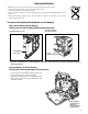
Chapter 3 Recording and playback 3-1 Cassette tapes Loading a cassette tape 1 Checking for tape slack Set the POWER switch to ON. When condensation has formed inside the unit, the HUMID display lights. Wait until this display is cleared before proceeding with the intended operation. Gently push in the reel using your finger and turn the reel in the direction of the arrow. If the reel fails to turn, it means there is no tape slack.
Chapter 3 Recording and playback 3-2 Basic procedures This section describes the basic steps for shooting and recording. Before actually departing to shoot scenes, carry out inspections to ensure that the system is functioning properly. Up to performing the switch settings Provide the power supply, and load the cassette. Next, set each switch as shown in the figure below, and then proceed to operate. * For details on how to perform these inspections, refer to “6-1 Inspections prior to shooting.
Chapter 3 Recording and playback Procedure for shooting From adjusting the white balance and black balance to stopping the recording From adjusting the white balance and black balance to stopping the recording 1 Select the filter to match the lighting conditions. the white balance has been stored in the memory 2-1 Ifahead of time: Set the WHITE BAL switch to “A” or “B.
Chapter 3 Recording and playback 3-3 Scene-to-scene continuity Maintaining continuity from one scene to the next at an accuracy of +1 frame or less can be assured simply by pressing the VTR START button or VTR button on the lens while the unit is in the rec-pause mode. If the unit is in a mode other than rec-pause, the point at which the scene-to-scene continuity is to be maintained must be located before recording is started. Scene-to-scene continuity during rec-pause 3 Press the lens RET button.
Chapter 3 Recording and playback 3-5 PRE-RECORDING function SDC905 By always storing a few seconds’ worth (maximum of 6 seconds) of audio and video data shot by the camera, it is possible to record video and audio signals a number of seconds before recording is actually started by pressing the VTR START button or the VTR button on the lens.
Chapter 3 Recording and playback When recording is to be suspended at any time When the recording is to be continued Press the STOP button. Recording is now suspended. O With the AJ-SDC905 SDC905 , the tape may continue to run since the unit will record the images stored in the memory until the moment when the button is pressed. Press the unit’s VTR START button or VTR button on the lens once more. One-shot recording is now started again.
Chapter 3 Recording and playback 3-7 RETAKE function 3-8 Rec-review function The RETAKE function ensures continuity with the previous cut on the tape when shooting is resumed. It is set by opening the screen from the SYSTEM SETTING page and selecting ON as the setting for the RETAKE MODE item by performing menu operations.
Chapter 4 Adjustments and settings for recording In order to achieve images with a consistently high picture quality with this unit, it is necessary to adjust the black balance and white balance as the individual conditions demand. To achieve a higher picture quality, it is recommended that the adjustments be performed in the following sequence: AWB (white balance adjustment) > ABB (black balance adjustment) > AWB (white balance adjustment). 4 Adjust the lens aperture.
Chapter 4 Adjustments and settings for recording When there is no time to adjust the white balance Auto tracking white balance setting Set the WHITE BAL switch to PRST. The white balance for the filter is achieved in accordance with the setting position of the FILTER control (outer). This unit comes with an auto tracking white balance (ATW) function for automatically tracking the white balance of the images in accordance with the lighting conditions. This function can be set in WHITE BAL switch B.
Chapter 4 Adjustments and settings for recording 4-1-2 Adjusting the black balance The black balance needs to be adjusted in the following cases: ≥ When the unit is used for the first time ≥ When the unit is used after it has not been used for a prolonged period of time ≥ When the unit is used in an ambient temperature which has fluctuated significantly ≥ When the value selected for the gain switch has been changed ≥ When the super gain setting has been performed using the USER MAIN, USER1 or USER2 button ≥
Chapter 4 Adjustments and settings for recording 4-2 Setting the electronic shutter This section describes the unit’s electronic shutter, its settings and operations. #< SHUTTER SELECT > SUPER V MODE POSITION1 SEL POSITION2 SEL POSITION3 SEL POSITION4 SEL POSITION5 SEL POSITION6 SEL 4-2-1 Shutter modes The table below lists the shutter modes in which the unit’s electronic shutter can be used as well as the shutter speeds which can be selected.
Chapter 4 Adjustments and settings for recording 4-2-3 Setting the synchro scan mode Items to be set and what is set The signals to be recorded are selected using REC SIGNAL. Proceed with operation by following the steps below. 1 Press the SHUTTER switch from ON to SEL to establish the SYNCHRO SCAN mode. SYNCHRO SCAN (+ and –) buttons SHUTTER switch 2 In the SYNCHRO SCAN mode, it is possible to change the shutter speed continuously within a range from 1/50.4 sec. to 1/248.0 sec.
Chapter 4 Adjustments and settings for recording 4-3-2 Selecting the recording system Open the screen from the SYSTEM SETTING page and select the format of the VTR to be used for recording using the REC MODE item by performing menu operations. For the detailed audio-related settings, open the and screens from the VTR MENU page and select the settings for the items by performing menu operations. For details, refer to “Chapter 7 Menu description tables.
Chapter 4 Adjustments and settings for recording Audio level meter in display window NDF SLAVE HOLD W GPS CTL VTCG TIME DATE P-iREC 1 Set the DISPLAY switch to UB. 2 Set the TCG switch to SET. 3 Set the user bits using the SHIFT button, UP (+) button and DOWN (–) button. SHIFT button: This is used to cause the digit that is to be set to flash. Each time it is pressed, the flashing digit moves to the right. UP (+) button: This increments the numerical value of the flashing digit by 1.
Chapter 4 Adjustments and settings for recording 4-5-2 Setting the internal clock’s date and time 1 2 3 4 5 6 7 8 9 10 Set the DISPLAY switch to UB. Press the HOLD button to cause DATE to be displayed in the display window. Set the TCG switch to SET. Set the date (year/month/day) using the SHIFT button, UP (+) button and DOWN (–) button. Press the HOLD button to cause TIME to be displayed in the display window. Set the time (hour/minutes/seconds) using the SHIFT button, UP (+) button and DOWN (–) button.
Chapter 4 Adjustments and settings for recording 4-5-3 Setting the time code 1 Set the DISPLAY switch to TC. 2 Set the TCG switch to SET. 3 Set the time code using the SHIFT button, UP (+) button and DOWN (–) button. 4 Example 2: When connecting a multiple number of units and using one of them as the reference unit MON OUT TC OUT Reference unit 4 TC IN Select the TCG switch position. Select “F-RUN” to advance the time code in the free-run mode or select “R-RUN” to advance it in the rec-run mode.
Chapter 4 Adjustments and settings for recording Concerning the user bit setting during external lock 4-5-5 Setting the UMID information When the unit’s time code is externally locked, only the time data is locked to the time data of the time code supplied from the external source. This means that the user bits can be set separately for each component.
Chapter 4 Adjustments and settings for recording 4-6 Menu displays on the viewfinder screen 4-6-1 Menu configuration 4-6-2 Basic menu operations USER MENU: Menu items are selected and entered using the MENU button and JOG dial button. The menus have a hierarchical configuration consisting of the main menu, sub menus and setting item menus. The data which has been set is written and saved in a nonvolatile memory.
Chapter 4 Adjustments and settings for recording 2 To increment the value Turn the JOG dial button to move the arrow (cursor) to the item which is to be set, and the sub menu screen appears when the JOG dial button is pressed. Turn the JOG dial button in the clockwise direction as viewed from the front of the camera.
Chapter 4 Adjustments and settings for recording 4-7 Viewfinder screen status displays 4-7-2 Viewfinder screen status display configuration Not only the images but the lamps and characters indicating the unit’s settings and operation statuses as well as the messages, center and safety zone markers, camera ID and other information are displayed inside the viewfinder. All the items that can be displayed are laid out inside the viewfinder as shown in the figure below.
Chapter 4 Adjustments and settings for recording Display item What is displayed Status when display appears 1 Extender EX2 This appears when the lens extender is in use. 2 MODE CHECK dedicated display area (STATUS: master gain, user switch gain) LOW/MID/HIGH –3 to 30 S.GAIN30/36/42/48 DS.GAIN6:/12:/20: This indicates the master gain setting. Example: LOW = 0 When S.GAIN and DS.GAIN functions have been allocated to the user switches, the corresponding gain values are displayed.
Chapter 4 Adjustments and settings for recording Display item 3 Camera warning and message display area (Displays related to the AWB, ABB and switch operations) What is displayed ABB ACTIVE ABB OK ABB BREAK ABB NG W-SHD ACTIVE W-SHD OK W-SHD BREAK W-SHD NG LVL OVER B-SHD READY B-SHD ACTIVE B-SHD OK B-SHD BREAK B-SHD NG B-SHD LVL OVER Status when display appears This appears during an ABB operation. This appears when the ABB operation has been completed satisfactorily.
Chapter 4 Adjustments and settings for recording Display item What is displayed Status when display appears 4 Information allocated to USER buttons UM: USER MAIN U1: USER1 button U2: USER2 button REC SW ATW ON/OFF D.ZOOM ON/OFF This appears only during MODE CHECK button operations while the USER button functions as the REC switch. This appears when the function for measuring the output brightness level (in % units for approx. 3 seconds for the area near the center marker) is ON.
Chapter 4 Adjustments and settings for recording Display item What is displayed Status when display appears > Zoom display Z00 to Z99 This indicates the amount of zoom. Note that this item is not displayed even if the display setting is ON if the lens is not equipped with a zoom position return function.
Chapter 4 Adjustments and settings for recording Viewfinder screen display selection Whether a display is to be shown or not can be selected on a menu.
Chapter 4 Adjustments and settings for recording 4-7-4 Display modes and setting changes/adjustment result messages #< VF DISPLAY > DISP CONDITION DISP MODE VF OUT VF DTL ZEBRA1 DETECT ZEBRA2 DETECT ZEBRA2 LOW LIGHT LVL ECU MENU DISP.
Chapter 4 Adjustments and settings for recording 3 4 When the JOG dial button is pressed, the arrow (cursor) moves to the ID input area, and the input mode is established. Press the JOG dial button again and turn it until the character to be set is displayed. When the button is turned, the character displayed is switched in the following sequence: Space: ∑ 7 letters: A—Z 7 numbers: 0—9 7 symbols: ’, >, <, /, – 5 Press the JOG dial button to enter the character.
Chapter 4 Adjustments and settings for recording 4-8 Menu-driven function setup 4-8-2 Selecting the video output signals The functions can be set up using the unit’s menus. The signals which are output from the VIDEO OUT connector and MON OUT connector can be selected.
Chapter 4 Adjustments and settings for recording 4-8-3 Selecting the F.AUDIO LEVEL control function 4-8-4 Allocating functions to the USER MAIN, USER1 and USER2 buttons This function enables the recording level to be adjusted using the F.AUDIO LEVEL control. To select this function, perform menu operations to open the screen from the VTR MENU page, and set whether to enable or disable the F.
Chapter 4 Adjustments and settings for recording UDIO CH1: The function for switching the channel 1 input signal is allocated. Each press advances the setting through the sequence FRONT > W.L.> REAR. Note that it is also possible to change the setting by operating the AUDIO IN switch. Whichever control is operated last takes precedence. AUDIO CH2: The function for switching the channel 2 input signal is allocated. Each press advances the setting through the sequence FRONT > W.L.> REAR.
Chapter 4 Adjustments and settings for recording 4-9-2 Setup card operations To format the setup card, save the setting data on the card or read the saved data from the card, first perform a menu operation to open the screen from the FILE page. #< CARD READ/WRITE > R.SELECT READ W.
Chapter 4 Adjustments and settings for recording Giving a title to the selected file Saving the data settings to the selected file 4 9 Turn the JOG dial button to move the arrow (cursor) to the “TITLE : ” item. When the title has been input, turn the JOG dial button to move the arrow (cursor) to the “:” position. < CARD READ/WRITE > R.SELECT READ W.SELECT WRITE CARD CONFIG TITLE READ < CARD READ/WRITE > :1 R.SELECT READ W.
Chapter 4 Adjustments and settings for recording the JOG dial button to move the arrow (cursor) to 13 Turn YES, and press the JOG dial button. When the data saving is completed, the following message appears. Loading the data of the selected file 4 Turn the JOG dial button to move the arrow (cursor) to the READ item. < CARD READ/WRITE > # R.SELECT READ W.SELECT WRITE CARD CONFIG TITLE READ TITLE: 1: ******** 2: ******** 3: ******** 4: ******** WRITE OK the MENU button to exit the menu operations.
Chapter 4 Adjustments and settings for recording If one of the following messages appears when the JOG dial button is pressed, the data cannot be loaded. Remedial action Error message READ NG NO CARD (setup card has not been inserted) Insert the card. READ NG FORMAT ERROR (formatting error) The card was formatted by a device other than the unit. Replace the card. READ NG NO FILE (file not found) Save the file data.
Chapter 4 Adjustments and settings for recording 3 When the JOG dial button is pressed, the following message appears. 5 Turn the JOG dial button to move the arrow (cursor) to the WRITE item. < SCENE > # READ USER DATA SCENE SEL READ WRITE RESET ;1 TITLE1 : ******** TITLE2 : ******** # READ? YES NO TITLE3 : ******** TITLE4 : ******** 4 Turn the JOG dial button to move the arrow (cursor) to YES, and press the JOG dial button.
Chapter 4 Adjustments and settings for recording 4 Press the JOG dial button to enter the scene file. 5 Turn the JOG dial button to move the arrow (cursor) to the READ item. 3 < SCENE > < SCENE > # READ USER DATA SCENE SEL READ WRITE RESET When the JOG dial button is pressed, the scene file number starts flashing. Turn the JOG dial button to select the scene file whose data is to be reset.
Chapter 4 Adjustments and settings for recording Appending titles to the setting data used for the scene files 1 Perform a menu operation to open the screen. 2 Turn the JOG dial button to move the arrow (cursor) to the scene file TITLE1, 2, 3 or 4 item where the title is to be appended. 8 When the JOG dial button is pressed, the arrow (cursor) returns to the TITLE1, 2, 3 or 4 item. 9 Turn the JOG dial button to move the arrow (cursor) to the WRITE item.
Chapter 4 Adjustments and settings for recording 4-9-5 How to return the menus settings to the user standard settings 4-9-6 How to return the menus settings to the factory standard settings The setting statuses of the unit’s menus can be returned to the user standard settings registered in 4-9-3. There are two ways to do this: one method is to read (load) the USER DATA as described in “4-9-3 How to use the user data” and the other enables the return without performing any menu operations.
Chapter 5 Preparation 5-1 Supplying the power A battery pack or an AC power source can be used as this unit’s power supply. 2 Insert the battery pack and slide it in the direction of the arrow. To use the battery pack, there is the following choice of makes of batteries: ≥Panasonic ≥Anton-Bauer ≥IDX ≥PACO ≥Sony ≥ Batteries of other makes can also be supported by changing the setting menu but no guarantees are made for the system when they are actually used with this unit.
Chapter 5 Preparation Using the BP-90 type battery pack 1 3 Remove the battery holder. Connect the plug of the battery pack to the connector inside the battery case, and insert the battery pack into the case. 5 Battery holder Label surface 2 Attach the battery case to the unit. 1 Connect the unit’s cable with the cable of the BP-90 type battery case. 2 Use a screwdriver to attach the BP-90 type battery case to the unit.
Chapter 5 Preparation Using the NP-1 type battery pack 1 Remove the battery holder. 2 Attach the NP-1 type battery case to the unit. 1 Tighten the mounting screws. 2 Tighten the power contact screws. 3 Insert the top of the detached cover in the direction shown by the arrows. 4 Align the holes in the bottom of the cover (metal part) with the holes at the bottom of the case, and use the screws to attach the case. When mounting the battery holder, take care not to pinch the connecting cord.
Chapter 5 Preparation 5-1-2 Using an AC power supply When the AJ-B75 AC adapter made by Panasonic is used 1 Connect the DC OUT connector on the AJ-B75 AC adapter to the DC IN socket on the unit. 5-2 Attaching the viewfinder and adjusting its position Refer to the instructions accompanying the viewfinder. A slide rail is required for attaching a viewfinder (AJ-VF15 or AJ-VF20W) other than the AJ-VF15B or AJ-VF20WB. O If you wish to install the slide rail, ask your dealer to obtain it as an accessory part.
Chapter 5 Preparation 5-3 Attaching the lens and performing the flange back and white shading adjustments 4 Push the cable into the cable clamp, and connect it to the LENS socket. Attaching the lens 1 Raise the lever for securing the lens, and detach the mount cap. LENS socket Lever for securing the lens Mount cap 2 Align the center mark of the lens with the groove in the top center of the lens mount, and attach the lens. Mark 3 62 Push down the lever for securing the lens to secure the lens.
Chapter 5 Preparation Adjusting the lens flange Adjusting the white shading of the lens If the subject is not focused properly in the telephoto and wide-angle modes during zoom operations, adjust the flange back (distance from the lens mounting surface to the imageforming surface). Once this adjustment is done, it need not be redone unless the lens is replaced. The white shading is adjusted as follows.
Chapter 5 Preparation 7 Set the lens aperture control to manual, and adjust it so that the zebra pattern covers the whole screen. Check that the lens aperture is between F4 and F11. ≥ The zebra pattern will not cover the whole screen if there is any unevenness in the lighting. In this case, make adjustments to the position of the lighting, etc. ≥ Make adjustments to the position of the lighting, etc. also when the lens aperture is not between F4 and F11.
Chapter 5 Preparation Storing the lens file data The white shading adjustment values can be stored in the unit as lens file data. 6 Press the JOG dial button again and turn it until the character to be set is displayed. When the button is turned, the character displayed is switched in the following sequence: Space: ∑ 7 letters: A—Z 7 numbers: 0—9 7 symbols: ’, >, <, /, –, •, a 7 Press the JOG dial button to enter the character.
Chapter 5 Preparation Reading the lens file data 1 Refer to steps 1 to 3 in “Storing the lens file data,” and enter the lens file. 2 Turn the JOG dial button to move the arrow (cursor) to the “READ” item. 3 When the JOG dial button is pressed, the following message appears. # READ? YES NO 4 Turn the JOG dial button to move the arrow (cursor) to YES, and press the JOG dial button. When reading is complete, “READ OK” is displayed, indicating that the lens file data has been read from memory.
Chapter 5 Preparation 5-4 Audio input signal preparations 5-4-2 When using an external microphone Prepare to connect the audio components which will supply the audio signals to the unit. First attach the AJ-MH700P mic holder (optional accessory). 5-4-1 When using the front microphone 1 Remove the screws used to attach the mic holder. The microphone of the AJ-MC700P mic kit (optional accessory) can be attached to the viewfinder. 1 Open the mic holder.
Chapter 5 Preparation 5-4-3 When using a wireless receiver When using a UniSlot ® wireless receiver When using an externally connected wireless receiver 1 Remove the slot cover, insert the wireless receiver, and screw it down. 2 Set the AUDIO IN switches to WIRELESS for the audio channels whose audio signals are to be recorded. Attach the wireless receiver when a wireless system is to be used. 1 Attach the wireless receiver to the camera attachment.
Chapter 5 Preparation 5-5 Mounting the unit on a tripod 5-6 Attaching the shoulder belt Shoulder belt Use the tripod attachment to mount the unit on a tripod. 1 Mount the tripod attachment on the tripod. Tripod attachment Tripod head 5 The tab opens when it is pressed. Take account of the center of gravity of the unit and that of the tripod attachment when selecting the attachment hole. Check that the diameter of the hole selected matches the diameter of the tripod head screw.
Chapter 5 Preparation 5-8 Attaching the rain cover Example showing use of the SHAN-RC700 rain cover Tighten the cord. Close using the fastener. Close using the fastener. 5-9 Connecting the extension control unit (AJ-EC3E) By connecting the AJ-EC3E extension control unit (optional accessory), some of the functions can be operated by remote control. When the AJ-EC3E is connected and the POWER switches on the unit and AJ-EC3E are set to ON, the unit is automatically set to the remote control mode.
Chapter 6 Maintenance and inspections 6-1 Inspections prior to shooting 6-1-2 Inspecting the camera unit Before setting off for a shooting session, perform the following inspections to verify that the system is functioning correctly. It is recommended that a color video monitor be used to check the images. 1 Set the zoom to the motorized zoom mode, and check its operations in this mode. Check that the image changes when the zoom is set to the telephoto and wide-angle positions.
Chapter 6 Maintenance and inspections 6-1-3 Inspecting the VTR unit 2. Automatic audio level adjustment function inspection Perform all the steps outlined in section “1. Tape travel inspection” through section “4. Earphone and speaker inspection” one after the other. 1 Set the AUDIO SELECT CH1 and CH2 switch to AUTO. 2 Set the AUDIO IN CH1 and CH2 switches to FRONT. 1. Tape travel inspection 1 Set the VTR SAVE/STBY switch to SAVE, and check that the VTR SAVE lamp inside the viewfinder lights.
Chapter 6 Maintenance and inspections 5. Inspection using external microphones 1 Connect external microphones to the AUDIO IN CH1 and CH2 jacks. 2 Set the AUDIO IN CH1 and CH2 switches to REAR. 3 Set the LINE/MIC/+48V selector switch on the back panel to MIC or +48V in accordance with the external mic’s power supply type. 6-1-4 Self-diagnosis function Simplified checks can be undertaken on the unit’s system at such times when, for instance, a color video monitor is not available.
Chapter 6 Maintenance and inspections 6-2 Maintenance 6-2-5 Replacing the backup battery 6-2-1 Condensation The backup battery is already installed when the unit is shipped. When it has discharged, the “BACK UP BATT EMPTY” display appears for 3 seconds on the viewfinder screen when the POWER switch is set to ON. Moreover, the time code value of the TCG will be set to “00:00:00:00” and the backup of the time code value will no longer be possible: this means that the backup battery should be replaced.
Chapter 6 Maintenance and inspections 6-2-6 Connectors and signals 1 2 3 4 DC IN GND NC NC +12V Matsushita part number K1AA104H0024 Maker part number HA16RX-4P(SW1) (Hirose Denki) 1 2 3 AUDIO IN GND AUDIO IN(H) AUDIO IN(C) Matsushita part number K1AB103A0007 Maker part number HA16PRM-3SG (Hirose Denki) 1 2 3 4 5 AUDIO OUT GND L CH OUT (H) L CH OUT (C) R CH OUT (H) R CH OUT (C) Matsushita part number K1AA105H0007 Maker part number HA16RD-5P (Hirose Denki) PUSH 4 3 2 6 1 2 1 3 1 5 4 2
Chapter 6 Maintenance and inspections 6-3 Warning system 6-3-1 Warning description tables When an error or a problem is detected immediately after the power is turned on or while an operation is underway, the WARNING lamp and lamps inside the viewfinder serve to alert the user. Items are displayed in the following sequence of priority: WARNING lamp > tally lamp > warnings inside the viewfinder. The display accords with this sequence when more than one error has occurred at the same time.
Chapter 6 Maintenance and inspections 5. HUMID Indications on LCD screen WARNING lamp 7. RF “HUMID” display lights if condensation is detected. “HUMID” display flashes for an additional 10 to 90 minutes after condensation detection is canceled. Indications on LCD screen “RF” display flashes (during standby and recording). WARNING lamp Flashes four times a second (during recording). Tally lamp Flashes four times a second (during recording).
Chapter 6 Maintenance and inspections 10. BATTERY NEAR END 11. TAPE NEAR END Indications on LCD screen The bar display that shows the remaining battery charge starts flashing. Indications on LCD screen The bar display that shows the remaining tape amount starts flashing. WARNING lamp Flashes once a second. WARNING lamp Flashes once a second (during recording). Tally lamp Flashes once a second. Tally lamp Flashes once a second (during recording). Viewfinder BATT LED starts flashing.
Chapter 6 Maintenance and inspections 6-3-3 Emergency eject If the cassette cannot be ejected by pressing the EJECT button, use a screwdriver or similar tool to press and turn the emergency eject screw. This enables the cassette to be removed. 1 Set the power to OFF. 2 Remove the rubber cap where shown in the figure. Insert a Phillips head screwdriver into the cross-shaped part of the emergency eject screw (red).
Chapter 7 Menu description tables 7-1 Menu configuration MENU USER MENU MAIN MENU SYSTEM SETTING ROP MATRIX COLOR CORRECTION LOW SETTING MID SETTING HIGH SETTING ADDITIONAL DTL SKIN TONE DTL KNEE/LEVEL GAMMA FLARE CAMERA SETTING PAINT OPTION MENU OPTION VF CAMERA ID SHUTTER SPEED SHUTTER SELECT USER SW SW MODE WHITE BALANCE MODE USER SW GAIN IRIS OPERATION How to open the menus USER MENU: Press MENU button to display. MAIN MENU: Hold down MENU button for 3 seconds or more to display.
Chapter 7 Menu description tables 7-2 SYSTEM SETTING 7-2-1 SYSTEM MODE Item/ Data storage REC SIGNAL Variable range CAM VIDEO 1394 For selecting the video input signals. CAM: The signals from the camera are recorded. VIDEO: The signals from the GENLOCK IN connector are recorded. 1394: The signals from the DVCPRO connector are recorded. CAM is always set when the power is next turned on after it being turned off.
Chapter 7 Menu description tables 7-2-2 OPTION MODE Item/ Data storage P.OFF GPS DATA Variable range HOLD CLEAR C U F COMPONENT OUT ON OFF C U F 1394 SPEED 0 : 63 AUTO For setting the input channel for the signals to be supplied to the DVCPRO connector. 0-63: The channel is fixed at the specified number. AUTO: The channel corresponding to the setting of the externally connected unit is selected.
Chapter 7 Menu description tables 7-2-3 REC FUNCTION Item/ Data storage Variable range Remarks ON ONE SHOT OFF For setting the INTERVAL REC function. ON (MEMORY): Interval recording is possible in singleframe units using memory. ONE SHOT: Recording is performed only once for the time set in the REC TIME item, after which it stops. OFF: Interval recording is not performed. 00s01f : 59s24f For setting the recording time (one cut). The shortest time is one frame.
Chapter 7 Menu description tables 7-2-4 OUTPUT SEL Item/ Data storage VIDEO OUT SEL Variable range For selecting the output signal of the VIDEO OUT connector. VBS: The normal composite signal is output. VF: The viewfinder’s Y signal is output. The status display is also superimposed. Y: The component Y signal is output. TC STATUS MENU ONLY For setting the type of characters to be superimposed onto the output signals of the VIDEO OUT connector and MON OUT connector. TC: The time code is displayed.
Chapter 7 Menu description tables 7-3 PAINT 7-3-2 MATRIX Item/ Data storage 7-3-1 ROP Item/ Data storage MASTER PED Variable range –200 : For setting the master pedestal level. For selecting the color correction table used to perform the adjustments. MATRIX R-G For performing the R-G color adjustment. S C U F E +31 U F E +200 –31 : For setting the H detail/V detail level. MATRIX R-B For setting the master gamma in 0.01 steps. MATRIX G-R : 85.0% For setting the master knee position in 0.
Chapter 7 Menu description tables 7-3-3 COLOR CORRECTION Item/ Data storage R (SAT/PHASE) Variable range –63 : +00 7-3-4 LOW SETTING Remarks For performing the red color correction (saturation and hue). Item/ Data storage $ MASTER GAIN : +00 : +00 For performing the color correction (saturation and hue) between red and magenta. H.DTL LEVEL : For performing the magenta color correction (saturation and hue). V.
Chapter 7 Menu description tables 7-3-5 MID SETTING Item/ Data storage $ MASTER GAIN Variable range –3dB : 9dB 7-3-6 HIGH SETTING Remarks For setting the master gain to –3, 0, 3, 6, 9, 12, 15, 18, 21, 24, 27 or 30 dB. Item/ Data storage $ MASTER GAIN 00 : For performing the H.DTL LEVEL setting. H.DTL LEVEL For performing the V.DTL LEVEL setting. V.DTL LEVEL For performing the DTL CORING setting. DTL CORING For performing the H.DTL FREQ setting. H.DTL FREQ.
Chapter 7 Menu description tables 7-3-7 ADDITIONAL DTL Item/ Data storage KNEE APE LVL Variable range OFF 1 2 7-3-8 SKIN TONE DTL Remarks Item/ Data storage For performing the KNEE APE LEVEL setting. $ SKIN TONE DTL : S C U F E 5 CHROMA DTL OFF 1 : S C U F E DTL GAIN(+) 5 –31 : Variable range S C U F E OFF For selecting ON or OFF for the skin tone DTL. SKIN TONE ZEBRA ON S C U F E OFF For selecting ON or OFF for ZEBRA in the SKIN TONE range. For performing the CHROMA DTL setting.
Chapter 7 Menu description tables 7-3-9 KNEE/LEVEL Item/ Data storage MASTER PED Variable range –200 : +010 7-3-10 GAMMA Remarks For performing the MASTER PEDESTAL setting. Item/ Data storage MASTER GAMMA ON OFF S C U F E KNEE POINT 70.0% : 85.0% : 50 : 99 (98) S C U F E $ WHITE CLIP For setting the mode which is to be established when the AUTO KNEE switch is at OFF. The KNEE POINT/SLOPE setting value is active when ON is selected. R GAMMA For setting the KNEE POINT position in 0.5% steps.
Chapter 7 Menu description tables 7-4 VF 7-3-12 CAMERA SETTINGS Item/ Data storage DETAIL Variable range ON 7-4-1 VF DISPLAYS Remarks For selecting ON or OFF for DTL (H, V). S C U F E OFF 2D LPF ON For selecting ON or OFF for the 2dimensional LPF that reduces cross color. S C U F E OFF HIGH COLOR ON OFF For selecting ON or OFF for the mode in which the dynamic range of the colors is expanded. ON S C U F E OFF For selecting ON or OFF for the gamma circuit.
Chapter 7 Menu description tables 7-4-2 VF MARKER Item/ Data storage TABLE Variable range A B OFF 1 2 3 4 For selecting the center marker. OFF: The center marker is not displayed. 1: + (large) 2: Center blank (large) 3: + (small) 4: Center blank (small) OFF 1 2 For selecting the type of safety zone frame. OFF: The safety zone frame is not displayed. 1: Box 2: Corner frames 80% For setting the position of the safety zone.
Chapter 7 Menu description tables 7-4-5 VF INDICATOR2 Item/ Data storage TAPE Variable range ON C U F E OFF BATTERY ON C U F E OFF AUDIO LVL ON C U F E OFF TC TCG TCR TCG/TCR OFF C U F E VTR WARNING ALWAYS NORMAL OFF C U F E SAVE LED SAVE& TAPE SAVE C U F E 7-4-7 !LED Remarks For selecting ON or OFF for the remaining tape amount display. GAIN(0dB) For selecting ON or OFF for the battery voltage display. GAIN (–3dB) For selecting ON or OFF for the audio level meter display. DS.
Chapter 7 Menu description tables 7-5 OPERATION 7-5-3 SHUTTER SELECT Item/ Data storage 7-5-1 CAMERA ID Item/ Data storage ID1: SUPER V MODE Variable range Remarks ********** CAMERA ID setting 1 ********** CAMERA ID setting 2 ********** CAMERA ID setting 3 Variable range FRM1 FRM2 C U F ID2: C U F ID3: C U F C U F E If READ FACTORY DATA is selected, this setting will be cleared.
Chapter 7 Menu description tables 7-5-4 USER SW Item/ Data storage Variable range USER MAIN SW 7-5-5 SW MODE Remarks INH S.GAIN DS.GAIN S.IRIS I.OVR S.BLK B.STR AUDIO CH1 AUDIO CH2 REC SW Y GET RET SW ATW C U F E D.ZOOM For allocating the USER MAIN switch function. INH S.GAIN DS.GAIN S.IRIS I.OVR S.BLK B.STR AUDIO CH1 AUDIO CH2 REC SW Y GET RET SW ATW C U F E D.ZOOM For allocating the USER1 switch function. USER1 SW USER2 SW INH S.GAIN DS.GAIN S.IRIS I.OVR S.BLK B.
Chapter 7 Menu description tables 7-5-6 WHITE BALANCE MODE Item/ Data storage FILTER INH Variable range ON OFF C U F E SHOCKLESS AWB OFF FAST NORMAL SLOW1 SLOW2 C U F E SLOW3 AWB AREA 25% 50% 90% C U F E AWB & ABB OFFSET ON OFF C U F E COLOR TEMP PRE 3200K : C U F E 5600K AWB A For selecting the AWB detection area. 25%: An area near the screen center equivalent to 25% of the screen is detected. 50%: An area near the screen center equivalent to 50% of the screen is detected.
Chapter 7 Menu description tables 7-6 FILE 7-5-8 IRIS Item/ Data storage A.IRIS LEVEL Variable range 000 : Remarks For setting the AUTO IRIS target value. 060 : C U F E 100 7-6-1 CARD READ/WRITE Item/ Data storage R.SELECT Variable range 1 For selecting the number of the file whose data is to be read. : A.IRIS PEAK/AVE 000 : 040 : 100 C U F E A.IRIS MODE NORM1 NORM2 CENTR For selecting the auto iris detection window.
Chapter 7 Menu description tables 7-7 MAINTENANCE 7-6-3 LENS FILE Item/ Data storage FILE NO. Variable range 1 Remarks For selecting the number of the lens file. : 8 READ For reading the data from the lens file. WRITE For writing the data in the lens file. TITLE 1-8 ************ Variable range READ USER DATA SCENE SEL COLOR CHECK Variable range ON OFF Remarks Item/ Data storage Variable range 4 READ For reading the data from the scene file. WRITE For writing the data in the scene file.
Chapter 7 Menu description tables 7-8 VTR MENU 7-7-4 BLACK SHADING Item/ Data storage CORRECT Variable range ON C U F E OFF DETECTION (DIG) — 7-8-1 VTR FUNCTION Remarks For selecting ON or OFF for the digital black shading compensation. For executing the digital black shading compensation. Item/ Data storage HUMID OPE Variable range ON OFF For selecting whether or not to continue operation when HUMID alarm state has occurred. ALL NORMAL For selecting how recording start is to be accepted.
Chapter 7 Menu description tables 7-8-2 BATTERY/TAPE 7-8-3 BATTERY SETTING1 Item/ Data storage Variable range BATTERY SELECT PRO14 TRIM14 HYTRON50 HYTRON100 HYTRON120 DIONIC90 DIONIC160 HP-90L BP-H120 NP-L50 ENDURA50 ENDURA80 BP-L60/90 NiCd14 NiCd13 NiCd12 TYPE A TYPE B For selecting the type of battery to be used. The remaining charge is detected in accordance with the battery which has been selected.
Chapter 7 Menu description tables Item/ Data storage HYTRON120 Variable range 2 / For enabling or disabling the selection made for the BATTERY SELECT item. 2 : The selection is enabled. / : The selection is disabled. AUTO MANUAL 11.0 : 13.1 : C U F DIONIC90 15.0 : DIONIC160 11.0 For selecting the voltage at which the battery charge is to be considered nearly depleted in 0.1 V steps when MANUAL has been selected as the setting for the menu item above.
Chapter 7 Menu description tables 7-8-4 BATTERY SETTING2 Item/ Data storage ENDURA80 Variable range Variable range For enabling or disabling the selection made for the BATTERY SELECT item. 2 : The selection is enabled. / : The selection is disabled. AUTO MANUAL For selecting how the voltage at which the battery charge is considered nearly depleted is to be set. AUTO: The voltage is set automatically. MANUAL: The voltage is set manually. NEAR END 11.
Chapter 7 Menu description tables 7-8-5 MIC/AUDIO1 Item/ Data storage TYPE A FULL Variable range Remarks Item/ Data storage 2 / For enabling or disabling the selection made for the BATTERY SELECT item. 2 : The selection is enabled. / : The selection is disabled. 12.0 For selecting in 0.1 V steps the voltage at which FULL is to be displayed. FRONT VR CH2 For selecting in 0.1 V steps the voltage at which the battery charge is to be considered nearly depleted. MIC LOWCUT CH1 For selecting in 0.
Chapter 7 Menu description tables 7-8-6 MIC/AUDIO2 Item/ Data storage FRONT MIC POWER Variable range 7-8-7 TC/UB Remarks ON OFF For selecting the phantom power supply for the front microphone. REAR MIC POWER ON OFF C U F For selecting the phantom power supply for the rear microphone. AUDIO OUT For setting the audio output circuit. OFF: The power to the output circuit is shut down, and the signals of the circuit are not output. ON: The signals of the audio output circuit are output.
Chapter 7 Menu description tables 7-8-9 VTR DIAG Item/ Data storage TCG SET HOLD Variable range ON OFF C U F FIRST REC TC REGEN PRESET C U F P.OFF LCD DISPLAY ON OFF C U F TC OUT TCG TCG/TCR C U F Remarks For selecting ON or OFF for the function that without fail uses what was previously set as the TCG value for recording when the TCG value had been set before the power was turned off and recording was then performed after the power was turned back on again.
Chapter 7 Menu description tables 7-9 OPTION MENU 7-9-1 OPTION Item/ Data storage ENG SECURITY Variable range ON OFF For selecting whether or not to place a restriction on the opening and closing of the MENU screen. ON: The MENU screen can no longer be opened. To release this restriction, consult your nearest service center. OFF:No restriction is placed on the opening and closing of the MENU screen. ON OFF For selecting whether or not to turn off the function that mixes the ID with the camera image.
Chapter 8 Specifications [GENERAL] Power supply: DC 12 V (11.0 - 17.0 V) Power consumption: 24 W SDC615 25 W SDC905 indicates safety information. Ambient operating temperature: 0°C to +40°C Storage temperature: –20°C to +60°C Ambient operating humidity: Within 10% to 85% (relative humidity) Continuous operation time: Approx. 120 min. (using the Hytron50 made by Anton Bauer) Dimensions (WaHaD): 129a204a313 mm (excluding handle) Weight: Approx. 4.
Chapter 8 Specifications Tape Transport System Time Code Input Connector Tape speed: DVCPRO: 33.854 mm/sec DVCPRO 50 SDC905 : 67.708 mm/sec Recording time: DVCPRO: 66 minutes (when AJ-P66MP is used) DVCPRO 50 SDC905 : 33 minutes (when AJ-5P33MP is used) Fast forwarding time: Approx. 1 min. 30 sec. (when AJ-P66MP is used) Approx. 1 min. 30 sec. (when AJ-5P33MP is used) Rewinding time: Approx. 1 min. 30 sec. (when AJ-P66MP is used) Approx. 1 min. 30 sec. (when AJ-5P33MP is used) TC IN (BNC): 0.
Panasonic Broadcast Europe Panasonic Marketing Europe GmbH Hagenauer Str.