Operating Instructions Memory Card Camera Recorder Model No. AJ- Before operating this product, please read the insructions carefully and save this manual for future use.
PLEASE NOTE: z When preparing to record important images, always shoot some advance test footage, to verify that both pictures and sound are being recorded normally. z Should video or audio recording fail due to a malfunction of this camera-recorder or the P2 cards used, we will not assume liability for such failure. Software information for this product 1.
Precautions for Use DO NOT REMOVE PANEL UNSCREWING. COVER BY To reduce the risk of electric shock, do not remove cover. No user serviceable parts inside. Refer servicing to qualified service personnel. CAUTION: TO REDUCE THE RISK OF FIRE OR SHOCK HAZARD AND ANNOYING INTERFERENCE, USE THE RECOMMENDED ACCESSORIES ONLY. WARNING: z TO REDUCE THE RISK OF FIRE OR SHOCK HAZARD, DO NOT EXPOSE THIS EQUIPMENT TO RAIN OR MOISTURE.
Attention/Attentie z Batteries are used for the main power source and memory back-up in the product. At the end of their useful life, you should not throw them away. Instead, hand them in as small chemical waste. z Voor de primaire voeding en het reservegeheugen van het apparaat wordt gebruikgemaakt van een batterij. Wanneer de batterij is uitgeput, mag u deze niet gewoon weggooien, maar dient u deze als klein chemisch afval weg te doen.
Contents Precautions for Use . . . . . . . . . . . . . . . . . . 3 Chapter 1 Introduction . . . . . . . . . . . . . . 8 4-4 Selecting Audio Input Signals and Adjusting Recording Levels . . . . . . . . . . . 35 1-1 Camera Unit Features . . . . . . . . . . . . . . . . 8 4-4-1 Selecting Audio Input Signals . . . . . . . . . . . . . 35 1-2 Recorder/player Features . . . . . . . . . . . . . 9 4-4-2 Adjusting Recording Levels. . . . . . . . . . . . . . . 36 1-3 System Configuration . . . . . . . . . .
4-10 Handling data. . . . . . . . . . . . . . . . . . . . . . 56 Properties. . . . . . . . . . . . . . . . . . . . . . . . . 83 4-10-1 Handling SD Cards . . . . . . . . . . . . . . . . . . . . .56 6-13-1 Clip Property . . . . . . . . . . . . . . . . . . . . . . . . . . 83 4-10-2 Formatting, Writing and 6-13-2 P2 Card Status Display . . . . . . . . . . . . . . . . . . 84 Reading an SD Card . . . . . . . . . . . . . . . . . . . .56 Chapter 7 Maintenance and Inspections . . . . . . . . . . . . . .
8-5 CAM OPERATION. . . . . . . . . . . . . . . . . 103 8-5-1 CAMERA ID . . . . . . . . . . . . . . . . . . . . . . . . . .103 8-5-2 SHUTTER SPEED . . . . . . . . . . . . . . . . . . . . .103 8-5-3 SHUTTER SELECT . . . . . . . . . . . . . . . . . . . .103 8-5-4 USER SW . . . . . . . . . . . . . . . . . . . . . . . . . . .104 8-5-5 SW MODE . . . . . . . . . . . . . . . . . . . . . . . . . . .104 8-5-6 WHITE BALANCE MODE . . . . . . . . . . . . . . .105 8-5-7 USER SW GAIN . . . . . . . . . . . .
Chapter 1 Introduction The AJ-SPX800E video camera-recorder integrates a camera unit equipped with three CCDs, incorporating a 2/3-inch on-chip lens featuring progressive drive technology, and a video recorder/player (VTR) that supports DVCPRO50, DVCPRO and DV formats. The camera offers a choice of interlaced scanning and progressive scanning modes.
1-2 Recorder/player Features / Multiple Slots / Voice Memos & Shot Marks The AJ-SPX800E is equipped with five slots for P2 cards. Up to five cards may be inserted in these slots for continuous recording. They also provide new recording capabilities specific to memory cards. z Hot-Swap recording The Hot-Swap capability allows cards not in use to be replaced without interrupting recording. This facilitates continuous recording.
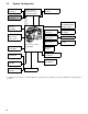
1-3 System Configuration Microphone kit: AJ-MC700P Unislot® wireless microphone receiver: Sennheiser EK3041 Extension control unit: AJ-EC3E Stereo microphone:* AJ-MC900G DIONIC90/160 HYTRON50/100/120 PRO14, TRIM14 Viewfinder: AJ-VF15B AJ-VF20WB Lens: (Bayonet type) Fujinon, Canon GPS unit: AJ-GPS900G Video camera-recorder AJ-SPX800E ENDURA50/80 BP-L60/90 NP-1 type Battery mount NP-L50 BP-90 type Battery mount BP-H120 HP-90L AC adaptor: AJ-B75 SDI output board: AJ-YA902AG Rain cover: SHAN-RC
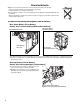
Chapter 2 Parts and their Functions 2-1 Power Supply and Accessory Mounting Section 2 POWER switch Lens mount cap Used to turn on/off the power. To remove the cap, raise the lens lever. When the lens is not mounted, replace the cap. Battery mount A battery pack from Anton/Bauer is mounted here. Lens cable/microphone cable clamp This clamp secures the lens and microphone cables.
2-2 Audio (input) Function Section MIC IN (microphone input) jack (XLR, 3-pin) A microphone (optional accessory) is connected here. Power for the microphone comes from this jack. A remote microphone may be connected. In this case, the power supply to the appropriate connector must be enabled through menu option FRONT MIC POWER or REAR MIC POWER. These options are found in the screen on the MAIN OPERATION page. A stereo microphone may be connected, but you will need to replace the connector.
2-3 Audio (output) Function Section AUDIO OUT connector (XLR, 5-pin) Speakers This connector outputs audio signals recorded on Channels 1/2 or 3/4. Output signals are selected with the MONITOR SELECT CH1/2 / CH3/4 selector switch. The speakers output EE sound during recording, and reproduced sound during playback. The speakers emit an alarm sound when the warning lamp blinks and/or the indicator activates. When the PHONES jack is connected with earphones, sound from the speaker is automatically muted.
2-4 Shooting and Recording/Playback Functions Section / Shooting and Recording (camera unit) CC/ND FILTER (filter selector) control Used to select a filter appropriate for illumination and colour temperature of the subject. When the menu option DISP MODE is set to “3”, switching this control displays the selected filter number in the viewfinder.
OUTPUT/AUTO KNEE selector switch MARKER SELECT button Used to select the video signals sent from the camera unit to the memory, viewfinder and video monitor. This button selects the marker information indicated on the viewfinder screen. It switches between two marker information indications, which can be selected using a menu option. Pressing this button once switches the indicated marker information from A (Marker A) to B (Marker B), and pressing again switches B to OFF (no marker).
OUTPUT SEL (output signal selection) switch USB 2.0 connector Used to switch the signals output from the VIDEO OUT and MON OUT connectors. A USB 2.0 cable is connected here. (To be supported in the near future.) MEM: CAM: OFF: In EE (recording) mode, video from the camera is output. In VV (playback) mode, playback signal from a P2 card is output. Video from the camera is output constantly. Video is not output, and the video camerarecorder operates in power-saving mode.
2-5 Menu Operation Section 2 MENU button Used to turn on/off the menu. JOG dial button With the menu open, this button is used to navigate through menu pages, select options and specify values. For directions on manipulating the menu, see [4-6 Menu Displays in the Viewfinder Screen]. SD card insertion slot An SD card (optional accessory) is inserted here. BUSY (operation mode display) lamp This lamp indicates the active status of the SD card. It stays illuminated when the card is active.
2-6 Time Code Section GENLOCK IN connector (BNC) TCG (time code selector) switch This connector is used to input a reference signal before the camera unit is gen-locked, or before the time code is externally locked. This switch is used to specify the stepping mode for the built-in time code generator. TC IN connector (BNC) This connector is used to input a reference time code when you externally lock the time code.
2-7 Warning and Status Display Functions 2-8 Display Window Functions P2 card/battery-remaining level indications Media-remaining space indication bar The bar indicates the remaining free space on each P2 card, using a seven-segment display. Each segment can represent either three or five minutes of remaining free space, depending on the value set through the menu option CARD REMAIN/. According to the set value, the segments disappear one-by-one.
2-9 LCD Monitor Mode indication W: Stays illuminated in 16:9 mode. DV: Stays illuminated when the recording/playback format is DV. GPS: Stays illuminated when radio waves are not received during GPS operation. GPS : Stays illuminated when radio waves are received during GPS operation. P-REC: Stays illuminated when PRE RECORDING is not set to 0 seconds, and blinks when recording is continued after the recording tally lamp has gone out.
2-10 Viewfinder Back tally lamp This lamp stays illuminated during shooting. It also blinks in synchronisation with the REC lamp in the viewfinder, and provides alerts. When the lever is positioned at [OFF], the back tally lamp is hidden. Eyepiece Diopter adjustment ring Use this to make adjustments in line with your diopter, in order to obtain optimum clarity in the viewfinder image. Viewfinder (optional accessory) During recording or playback, the viewfinder displays the video image in monochrome.
Chapter 3 Recording and Playback 3-1 P2 Cards Inserting P2 Cards 3 Insert a P2 card into the P2 card slot until the EJECT button pops up. When using the camera-recorder for the first time, be sure to set the time data beforehand. On how the time data is set, see [4-5 Setting Time Data]. 1 Turn on the POWER switch. EJECT button The card must be inserted with the logo right way up. 4 POWER: ON 2 Tilt up the popped-up EJECT button, to lock-in the P2 card.
Removing P2 Cards To Prevent Accidental Erasure of P2 Card Content 1 To prevent the content of a P2 card being accidentally erased, position the write-protect switch on the P2 card at [Pprotect]. 2 3 While pressing down the slide lock button, move the slideout door to the left. The door opens. Tilt down the EJECT button. Then, depress the EJECT button to release the P2 card so that you can remove it.
3-2 Basic Procedures This section describes the basic procedure for shooting and recording. Before you embark on a shoot, pre-inspect your system to ensure that it works properly. * For directions on inspecting your video camera-recorder, see [7-1 Inspections Before Shooting]. 3 Insert a charged battery pack. When a battery and P2 cards are installed, set the switches as detailed below, before starting to use your AJ-SPX800E.
Shooting White/Black balance adjustment to recording completion White/Black Balance Adjustment to Recording Completion For shooting, follow the steps below. 1 Select a filter according to light conditions. 2AWhen the white balance is saved: 3 Position the WHITE BAL switch to [A] or [B]. 2BWhen the white or black balance is not saved and you have no time to adjust the white balance: Position the WHITE BAL switch to [PRST].
3-3 Normal Recording Pressing either the REC START/STOP button, REC button on the handle or VTR button at the lens starts recording of video and sound on the P2 card. A cluster of data that consists of video and sound generated through a shooting action, together with such added information as a voice memo, is called a “clip”. Even if a P2 card has just been inserted, or the power has been just turned on, you can start recording using the internal memory of the AJ-SPX800E.
3-5 Loop Recording 3-6 When two or more P2 card slots contain cards, this function allows the target P2 card to be switched in order. Even when the free space of a P2 card is used up, this function continues recording while erasing existing data. To use this function, the menu option LOOP REC MODE must be set to “ON” The option LOOP REC MODE can be found in the
3-7 Normal and Variable Speed Playback The PLAY/PAUSE button provides monochrome playback through the viewfinder and colour playback on the LCD monitor. A colour video monitor connected to the VIDEO OUT or MON OUT connector of the AJ-SPX800E also provides colour playback. When the extension board AJ-YA902AG is attached, the VIDEO OUT connector outputs an SDI playback (to view the playback, the OUTPUT SEL switch on the side panel must be positioned to [MEM]).
Associating Voice Memos with a Clip The portion of the clip with which a voice memo is associated depends on when the voice memo is recorded. A voice memo recorded during recording or playback is associated with the picture in view at the time the VOICE MEMO button is pressed. A voice memo recorded when recording is paused is associated with the beginning picture of the immediately preceding clip.
Chapter 4 Adjustments and Settings for Recording To record high-quality video with the AJ-SPX800E, the black and white balances must be adjusted according to conditions. For higher quality, it is recommended that the adjustments should be made in this order AWB (white balance adjustment) ABB (black balance adjustment) AWB (white balance adjustment).
Detection area for the white balance Retaining white balances The detection area for the white balance is selectable between 90%, 50% and 25%, using the menu option AWB AREA. This option can be found in the screen, which is accessible from the CAM OPERATION page. The detection area is factory-set to 25%. Each value in memory is retained even if the video camerarecorder is turned off; it will not be lost until the white balance is re-adjusted.
4-1-2 Adjusting the Black Balance The black balance must be adjusted when: z You use your AJ-SPX800E the first time; z Your AJ-SPX800E has not been used for some time; z The ambient temperature has changed substantially; z The gain switchover value has been changed; or z S.GAIN (super gain) has been set with the USER MAIN/ USER1/USER2 button. 1 Set the switches as illustrated below. AUTO W/B BAL switch: Used to perform ABB.
4-2 Setting the Electronic Shutter 6+877(5 6(/(&7 ! This section provides a description of the electronic shutter, together with setting and handling directions. 4-2-1 683(5 9 02'( )50 326,7,21 6(/ 326,7,21 6(/ 326,7,21 6(/ 326,7,21 6(/ 326,7,21 6(/ 326,7,21 6(/ Shutter Modes The table below shows the shutter modes and speeds for the electronic shutter provided in your AJ-SPX800E.
4-2-3 Placing the Camera-recorder in SYNCHRO SCAN Mode To place the camera-recorder in SYNCHRO SCAN mode, follow the steps below. 1 Press the SHUTTER switch positioned at [ON] towards [SEL], to place the camera-recorder in SYNCHRO SCAN mode. SYNCHRO SCAN ADJUSTMENT buttons (+/–) 4-3 Selecting Recording Signals and Recording System The AJ-SPX800E is capable of utilising user-selected recording signals and format. 4-3-1 Selecting the Recording Signals.
4-4 z When “VIDEO” is selected for the menu option REC SIGNAL, non-standard signals output from the GENLOCK IN connector, may degrade video quality. z When “PROG.” is specified for the menu option V.RES (25P), segmented-frame video is recorded, allowing you to perform completely progressive editing. However, adding vertical details (V.DTL) can makes the video appear unnatural. For these reasons, it is recommended that V.DTL be set to 0.
z Audio Channels 1 and 2 always receive the signals selected with the AUDIO IN CH1 and CH2 switches. z When the extension board AJ-YA902AG (optional accessory) is attached, 4-channel recorded audio signals are SDI-output, as is. 3 While checking the audio channel level meter in the display window or the audio level meter in the viewfinder, adjust the AUDIO LEVEL CH1/CH2 control. Note that if the level exceeds the top bar (0 dB), the word OVER illuminates to show that the input level is excessive.
4-5 Setting Time Data 4-5-1 Setting the User Bits Card continuity provided by the user's bit The user bits allow information, including memos that use up to eight-digit base 16 numbers (date and time), to be recorded in the secondary code area.
4-5-2 1 2 3 4 5 6 7 8 Setting the Internal Clock’s Date and Time Position the DISPLAY switch at [UB]. Press the HOLD button to display a date in the display window. Position the TCG switch at [SET]. Use the CURSOR and SET buttons to set the year, month and day (Y/M/D). Note that any later than 2030 cannot be set. Press the HOLD button to display a time in the display window. Use the CURSOR buttons to set the hour, minute and second (h/min/s).
4-5-3 1 2 3 Setting the Time Code Position the DISPLAY switch at [TC]. Position the TCG switch at [SET]. Use the CURSOR buttons to set the time code. The time code setting range extends from 00:00:00:00 to 23:59:59:24. button: button: button: button: 4 Shifts the target (blinking) digit to the right. Shifts the target (blinking) digit to the left. Advances the blinking number by one digit. Winds back the blinking number by one digit. Change the position of the TCG switch.
To externally lock the time code: Follow the steps below. 1 2 3 4 5 Turn on the POWER switch. Position the TCG switch at [F-RUN]. Position the DISPLAY switch at [TC]. Set the menu option GENLOCK to “EXT”. This option can be found in the screen, which is accessible from the SYSTEM SETTING page. Supply a phase-relationship reference time code (that conforms to the time code requirements) and reference video signals to the TC IN and GENLOCK IN connectors, respectively.
4-5-5 Providing an ID to the Camera The camera ID is specified through the screen. The ID can include up to 10 alphanumeric characters, symbols, and/or spaces. When the settings menu is displayed, outputting colour bar signals does not indicate the camera ID. 1 Go to the screen from the CAM OPERATION page. 4-5-6 Setting UMID Information The AJ-SPX800E supports UMID metadata.
4-5-7 Mode Check Screen Displays (MODE CHECK button function) The viewfinder can display a screen that allows you to check the settings and status of the AJ-SPX800E. Each press of the MODE CHECK button switches the screen as follows: STATUS screen !LED screen FUNCTION screen AUDIO screen No indication 4-6 Menu Displays in the Viewfinder Screen 4-6-1 Menu Configuration USER MENU: USER MENU is factory-set.
4-6-2 Setting Menu Options The menu options are set with the MENU and JOG dial buttons. The menu comprises main menu, sub-menus and options menus. The data specified through menu options are written and saved in the internal memory of the AJ-SPX800E. This section describes how to set options in MAIN MENU. The other menus can be configured in the same manner (the method of displaying the menu screen depends on the particular menu).
5 4-6-3 To increase the value: Turn the JOG dial button clockwise, as seen from the front of the camera. To decrease the value: Turn the JOG dial button anti-clockwise, as seen from the front of the camera. Each turn of the dial switches the value by one step. A quick turn changes the value rapidly; a slow turn makes a fine adjustment. Go to the USER MENU SELECT page from MAIN MENU. Then, open relevant options menu screens to select options to add to USER MENU.
4-7 Viewfinder Screen Status Displays In addition to video images, the viewfinder displays lamps and text that indicate the settings and operating status of the AJSPX800E, together with messages, a centre marker, a safety zone marker and the camera ID. 4-7-1 Lamps in the Viewfinder Screen 4-7-2 Viewfinder Status Indication Layout The indications are arranged as illustrated below. J 6 ' = N J O 5 ( & 9 (; .
Information Item Indication Camera Shooting Mode Camera shooting mode (progressive or interlaced) Extender EX2 Lens extender used. MODE CHECK Indication Area LOW/MID/HIGH –3 to 30 S.GAIN 30/36/42/48 DS.GAIN 6 /12 /20 Value set for the master gain Example: LOW: 0 Gain value to which S.GAIN and DS.GAIN are assigned GAIN (0 dB) GAIN (–3 dB) DS.GAIN SHUTTER WHITE PRE. EXTENDER BLACK STR. MATRIX COLOR COR. FILTER SUPER V 50M/25M/DV ATW D.ZOOM Gain status Gain status DS.
Information Item Indication Camera Warning and AWB A ACTIVE AWB B ACTIVE Report Area AWB A OK _._K (related to AWB, ABB AWB B OK _._K and switch settings) AWB BREAK _._K AWB NG COLOR TEMP LOW COLOR TEMP HIGH LEVEL OVER LOW LIGHT TIME OVER AWB PRESET _._K ATW MODE CHECK FILTER AWB A VAR _._K AWB B VAR _._K ABB ACTIVE ABB OK ABB BREAK ABB NG W-SHD ACTIVE W-SHD OK W-SHD BREAK W-SHD NG LVL OVER B-SHD READY B-SHD ACTIVE B-SHD OK B-SHD BREAK B-SHD NG (Switch changeover indication) WHITE: # _.
Information Item System information and warnings Indication SYSTEM ERROR-__ TURN POWER OFF REC WARNING BACKUP BATT EMPTY WIRELESS-RF EOM BOS EOS CANNOT REC CANNOT PLAY VOICE CANNOT REC VOICE REC VOICE OFF VOICE PLAY MARK ON/OFF UPDATING USB DRIVE THUMBNAIL OPEN Voice memo indication Voice memo being recorded. When the free space for voice memos is less than one minute, the indication blinks.
Information Item P2 card remaining free space Indication ___min END WP LOOP INFO P2 _/_ Status The indication “___min” stays illuminated under normal conditions or blinks when the remaining level is near zero. When the card space is used up, “END” comes on. The P2 card is write-protected. The camera-recorder is in LOOP REC mode. When loop recording cannot be performed, for example because the P2 card has no free space, the indication blinks. P2 card being recognised.
P2 Card Remaining Free Space/capacity Indication Status of AJ-SPX800E Under normal conditions Recording status Other than LOOP REC mode LOOP REC mode During MODE CHECK Other than LOOP REC mode Menu option P2 CARD REMAIN* P2 card remaining free space indication P2 card remaining free space indication (during MODE CHECK) TOTAL The total remaining free space of all P2 cards loaded in the P2 card slots is indicated in minutes.
4-7-4 Display Modes and Setting Changes/adjustment Result Messages 9) ',63/$< ! ',63 &21',7,21 1250$/ ',63 02'( 9) 287 < 9) '7/ =(%5$ '(7(&7 =(%5$ '(7(&7 =(%5$ 6327 /2: /,*+7 /9/ (&8 0(18 ',63 2)) 0 ,1',&$725 2)) 0$5.
4-7-5 Setting the Marker Displays Markers The centre, safety zone, safety zone area and frame markers may be set to ON or OFF, along with specifications of the marker types. To set and select markers, go to the screen from the VF page and select the appropriate options. For directions on navigating the menu, see [4-6-2 Setting Menu Options]. Centre marker Safety zone 9) 0$5.(5 ! ޓޓޓޓޓޓޓޓޓޓޓޓޓޓޓޓޓޓޓޓޓޓޓޓޓޓޓޓޓޓޓޓޓޓޓޓޓޓޓޓޓޓ0.5 $ 7$%/( $ &(17(5 0$5.
4-8 Adjusting and setting the LCD monitor Using the LCD Monitor 1 2 Turn on the POWER switch of the AJ-SPX800E. 5 Through the menu option LCD MON CHAR, specify whether or not the LCD should display the same characters as the viewfinder. This menu option can be found in the
4-9 Menu-driven Function Setup Each function is set up using the menu system. 4-9-1 Setting the Switchover of USER SW GAIN In addition to the standard L/M/H gain mode, the AJ-SPX800E supports S.GAIN (super gain) mode, featuring greater than 30dB analog gain-up, together with DS.GAIN (digital super gain) mode, storage-type gain-up based on progressive drive technology. To make use of this feature, you need to specify desired gains through the menu options S.GAIN and DS.GAIN. For example, if the S.
4-9-4 Assigning Functions to USER MAIN, USER1 and USER2 Buttons The USER MAIN, USER1, and USER2 buttons can be assigned user-selected functions. To select desired functions, use the menu options USER MAIN SW, USER1 SW and USER2 SW. These options can be found in the screen, which is accessible from the CAM OPERATION page. 86(5 6: ! 86(5 0$,1 6: 6/27 6(/ 86(5 6: 6 *$,1 86(5 6: '6 *$,1 Selectable Functions INH: S.GAIN: DS.GAIN: S.IRIS: I.OVR: S.BLK: B.STR: D.
4-10 Handling data 4-10-2 Setting Data Using an SD Card An SD card (optional accessory) can be used as a setup card that stores up to eight files of settings menu specifications. This data allows you to quickly reproduce an optimum state. 4-10-1 Formatting, Writing and Reading an SD Card To format an SD card, write settings data or read data on an SD card, navigate the menu to the screen from the FILE page.
4 To write set data on an SD card: To format the SD card, turn the JOG dial button to move the cursor to YES. Then, press the dial button. When the SD card has been formatted, the following message appears: 1 Navigate the menu to the screen. To select a file number: 2 Turn the JOG dial button to move the cursor to the option [W. SELECT]. Then, press the dial button.
6 Turn the JOG dial button until a desired character appears. The characters that appear are switched in the following order: Space: Ð Alphabetical characters: Ð Numerals: Ð Symbols: 7 8 A to Z 0 to 9 ', >, <, /, - Press the JOG dial button to accept a desired character. Turn the JOG dial button to move the cursor to the next digit (clockwise), and repeat Steps 6 - 7 to set characters (up to eight characters).
To read data on an SD card: 1 Turn the JOG dial button to move the cursor to the option [SD CARD READ/WRITE]. Then, press the dial button. 6 Turn the JOG dial button to move the cursor to YES. Then, press the dial button. When the data has been written, the following message appears: To select a file number: 2 Turn the JOG dial button to move the cursor to the menu option [R. SELECT]. Then, press the dial button.
4-10-3 How to Use the User Data It is possible to transfer settings and other data to the user area of the internal memory of the AJ-SPX800E. This data allows you to quickly reproduce an optimum setup state. To write data, go to the screen from the FILE page. To read the written user data, go to the screen from the FILE page. ,1,7,$/,=( ! 5($' )$&725< '$7$ :5,7( 86(5 '$7$ 5(6(7 /(16 ),/(6 4 5 Turn the JOG dial button to move the cursor to YES. Then, press the dial button.
4-10-4 How to Use Scene File Data It is possible to write the settings data into the scene file area of the internal memory of the AJ-SPX800E, or to read data written in this area. Four types of scene files are available. This data allows you to quickly reproduce an optimum setup state. TITLEs 1 - 3 are factory-assigned the defaults for the AJSPX800E; TITLE 4 is assigned the parameter for FILMLIKE. The setting for TITLE 4 can be changed. 7 8 Turn the JOG dial button to move the cursor to YES.
To read settings data for scene files: To return data for scene files to their defaults: 1 2 1 2 3 Navigate the menu to the screen. Turn the JOG dial button to move the cursor to the option SCENE SEL. Press the JOG dial button to blink scene file numbers. Then, turn the dial button to select a desired scene file number. 3 6&(1( ! 7,7/( 7,7/( 7,7/( 7,7/( 7,7/( 7,7/( 7,7/( 7,7/( Press the JOG dial button to accept the scene file.
To title settings data for scene files: 1 2 Navigate the menu to the screen. 10 Press the JOG dial button to display the following message: Turn the JOG dial button to move the cursor to the option [TITLEs 1 - 4] for the appropriate scene file. 6&(1( ! 5($' 86(5 '$7$ 6&(1( 6(/ 5($' :5,7( 5(6(7 :5,7(" <(6 12 7,7/( 7,7/( 11 Turn the JOG dial button to move the cursor to YES. Then, 7,7/( 7,7/( press the dial button.
Chapter 5 Preparation 5-1 Power Supply A battery pack or AC power can be used as the power supply for the camera-recorder. Using a Battery Pack Battery packs from the following manufacturers can be used: • Panasonic • Anton/Bauer • IDX • PACO • Sony The Anton/Bauer battery holder includes both a power supply output connector for lighting and a lighting control switch, which are convenient when attaching a light.
When using a BP-90 type battery pack. 1 Remove the battery holder. 3 Connect the battery pack plug to the socket inside the battery case, and insert the battery pack into the case. Label surface Battery holder 2 Attaching the battery case to the camera-recorder. Connect the cable on the camera-recorder to the cable on the battery case (BP-90 type). Using a screwdriver, secure the battery case (BP-90 type) to the camera-recorder.
Using an NP-1 type battery pack. 1 2 3 Tighten the mounting screws. Tighten the power contact screws. Insert the upper part of the removed cover in the direction of the arrow. Align the holes in the bottom part (metal part) of the cover with the holes in the case, and secure the cover with the screw. Setting the battery type. Select the battery type listed under BATTERY SELECT. Select BATTERY SELECT from the screen on the MAIN OPERATION page.
5-1-2 Using an AC Power Supply 5-2 When using the Panasonic AJ-B75 AC adapter 1 Plug the AJ-B75 DC OUT connector into the camerarecorder’s external DC input socket. Mounting the Viewfinder and Adjusting its Position Please refer to the viewfinder instruction manual. Note: A slide rail is required to mount any viewfinder other than models AJ-VF15B or AJ-VF20WB.
5-3 Mounting the lens and Performing the Flange Back and White Shading Adjustments Mounting the Lens 1 If images are not clearly focused at both telephoto and wideangle positions during zoom operations, adjust the flange back (distance from the lens mounting surface to the image formation surface). Once adjusted, the flange back does not need to be re-adjusted as long as the same lens is mounted on the camera. Raise the lens clamping lever and remove the mount cap.
Adjusting the Lens White Shading Take the following steps to adjust the white shading: Vertical colouring may occur near the open position of the lens iris, even after adjusting the white shading. This phenomenon, however, is a characteristic of the lens or optical system. It does not indicate a malfunction. 1 2 3 4 Mount the lens on the camera. Be sure to connect the lens cable. Set the electronic shutter to [OFF], the gain to [L (0dB)], and the ASPECT option to “16:9”.
This completes the white shading adjustment. The compensation values are stored in the non-volatile internal memory. Therefore, re-adjusting the white shading is not required, even after the camera-recorder power has been turned off. 6 Space: Ð Alphabetical characters: Ð Numerals: Ð Symbols: Storing the Lens File Data The white shading compensation values can be stored in the internal memory as lens file data.
Reading out the Lens File Data 1 2 3 Resetting Lens File Data to Factory Standard Settings Select the lens file No. to read out by following Steps 1 to 3 in the [Storing the Lens File Data] section. The lens file data can be reset to the standard setting values that were set when the camera was shipped from the factory. From the FILE page, open the screen. Turn the JOG Dial button to move the cursor to [READ:]. 1 Press the JOG Dial button and the following message appears.
5-4 Preparing for Audio Input 5-4-2 When Using a Wireless Receiver Take the following steps to prepare the camera for connecting audio input devices. Using an External Wireless Receiver 5-4-1 1 2 When Using the Front Microphone The AJ-MC700P microphone kit (optional) microphone that can be mounted on the camera. 1 includes a Mount a wireless receiver when using a wireless system. Open the microphone holder. Mount the wireless receiver on the camera attachment.
When Using the Unislot® Wireless Receiver 1 Remove the cover to insert the wireless receiver and secure it with the screws. 5-5 Mounting the Camera on a Tripod When mounting the camera on a tripod, use the tripod attachment supplied with the camera. 1 Mount the tripod attachment on the tripod. Tripod Attachment Pan head 5 2 Set the AUDIO IN switch to [W.L.] depending on the audio channel to be recorded.
5-6 Attaching the Shoulder Strap Shoulder Strap 5-8 Connecting the AJ-EC3E Extension Controller Some functions can be remote-controlled when the AJ-EC3E extension control unit (optional) is connected to the camera. When the AJ-EC3E is connected, the camera automatically enters remote control mode after the power switches of both the camera and the AJ-EC3E are turned ON. Press to open the hook. Controller Cable AJ- To detach the shoulder strap, first open the hooks, then detach the strap.
5-9 Attaching the Front Audio Level Control Knob If you use the Front Audio Level control frequently, attach the accessory knob so that it can be easily operated. Front Audio Level Control Screw Knob (Accessory) Î Marks Screw (Accessory) 5 Remove the screw in the centre of the Front Audio Level control, and attach the accessory knob using the screw (included). When attaching the knob, be sure to align the marks on the control with the marks on the knob.
Chapter 6 Manipulating Clips with Thumbnails A clip is a data group that includes the images and voices created from one shooting session, together with additional information such as voice memos and meta data. The following manipulations can be performed using the cursor and SET buttons, while checking the images displayed on the LCD monitor: z Playback, delete or restore the clip. z Add a voice memo to the clip. z Add or delete a shot mark on the clip thumbnail. z Format P2 cards and SD cards.
6-2 Thumbnail Screen Time Display Press the THUMBNAIL button to display the thumbnail screen on the LCD monitor. Pressing the THUMBNAIL button again returns the display to the regular display. When switching is done from the regular screen display to the thumbnail screen display, all the clips will be displayed on the thumbnail screen. Also, pressing the MENU BAR button in the thumbnail screen moves the pointer to the menu bar and enables thumbnail menu manipulation.
6-3 Selecting Thumbnails 6-4 Multiple thumbnails can be randomly selected in the thumbnail screen. 1 2 Use the cursor buttons to move the pointer (yellow frame) to the desired clip and press the SET button. The frame around the selected thumbnail changes to a blue frame. Press the SET button again to deselect the clip. Additional clips can be selected by repeating Step 1. 1 2 3 It is possible to display only the selected thumbnails in the thumbnail screen for playback.
6-5 Switching the Thumbnail Display The display can be switched so that only those clips matching the specified conditions are displayed in the thumbnail screen. 1 2 6-6 Shot Mark A shot mark can be added to a clip thumbnail to distinguish this clip from the others. 1 Press the THUMBNAIL button. The thumbnail screen appears on the LCD monitor. 2 Press the MENU BAR button. The pointer moves to the menu bar. 3 Press the THUMBNAIL button. The thumbnail screen appears on the LCD monitor.
6-7 Voice Memo A voice memo is audio data that can be attached to the clip separately from the voice recorded during shooting. A voice memo can be attached during recording. Please refer to [3-8 Voice Memo Function] for more information. 6-7-1 1 2 3 5 6 Playing Back Voice Memos Press the THUMBNAIL button. The thumbnail screen appears on the LCD monitor. 7 Press the MENU BAR button. The pointer moves to the menu bar. From the MENU BAR, select THUMBNAIL VOICE MEMO CLIPS.
6-7-3 1 2 3 Deleting Voice Memos 6-9 Perform Steps 1 to 4 in the [6-7-1 Playing Back Voice Memos] section to select the voice memo in the clip. Restores clips that are defective as a result of sudden poweringdown during recording, or removal of the P2 card being accessed. Move the pointer over the clip you want to delete, and press the MENU BAR button. The pointer moves to the menu bar. From the menu bar, select OPERATION DELETE. YES and NO appear to confirm deletion.
6-10 1 2 3 4 5 Formatting a P2 Card Press the THUMBNAIL button. The thumbnail screen appears on the LCD monitor. Press the MENU BAR button. The pointer moves to the menu bar. From the menu bar, select OPERATION FORMAT. The following screen appears. Select the slot number for the P2 card you want to format. Select EXIT if formatting is not required. The following screen appears. Use the cursor buttons and the SET button to select YES.
6-12 Setting the Thumbnail Display Mode 6-13 Properties The clip’s properties and the P2 card’s status are displayed. The thumbnail display mode can be customised to suit your preferences. 6-13-1 1 From the menu bar, select PROPERTY CLIP PROPERTY. The following screen appears. 2 3 Press the THUMBNAIL button. The thumbnail screen appears on the LCD monitor. Clip Property Press the MENU BAR button. The pointer moves to the menu bar. From the menu bar, select THUMBNAIL SETUP.
Clip Meta Data Displays more detailed data about the clip. Use the cursor buttons to move the pointer, and press the SET button to check the detailed content. The underlined items are automatically set during shooting. Other items can be input on your personal computer, etc. GLOBAL CLIP ID: Displays the global clip ID indicating the shooting conditions of the clip. VIDEO: Displays [FRAME RATE] (clip frame rate), [PULL DOWN] (pulldown method), and [ASPECT RATIO] (aspect ratio).
Chapter 7 Maintenance and Inspections 7-1 Inspections Before Shooting Make sure you check that the system is operating normally before embarking on a shoot. We recommend using a colour video monitor to check the image. 7-1-1 1 2 7-1-2 1 2 Preparing for Inspections Mount a charged battery pack. Turn the power switch ON and check that 5 or more BATT indication marks appear. z If fewer than 5 BATT indication marks appear, replace the battery with a fully-charged battery.
7-1-3 Inspecting the Memory Recording Functions Make sure you successively carry out the inspections from [1. Inspecting the P2 Card Recording] to [4. Inspecting the Earphone and Speaker]. 2. Inspecting the Audio Level Automatic Adjustment 1 2 3 1. Inspecting the P2 Card Recording 1 2 3 4 Check on the display inside the viewfinder that the remaining P2 card recording capacity is sufficient.
6. Inspection of the clock, time code, and user bits 1 2 3 4 5 6 7 Set the user’s bit as required. Please refer to [4-5-1 Setting the User Bits] for the setting procedures. Set the time code. Please refer to [4-5-3 Setting the Time Code] for the setting procedures. 7-2 Maintenance 7-2-1 Cleaning Inside the Viewfinder z Do not use thinner or other solvents to remove dirt from the viewfinder. z Wipe the lens with a commercially available lens cleaner. z DO NOT wipe the mirror.
7-2-4 Connector Signals DC IN 1 2 3 4 GND NC NC +12V 1 2 3 Panasonic Part No. K1AA104H0024 Manufacturer Part No. HA16RX-4P(SW1) (Hirose Electric Co.) AUDIO OUT AUDIO IN 1 2 3 4 5 GND AUDIO IN (H) AUDIO IN (C) Panasonic Part No. K1AB103A0007 Manufacturer Part No. HA16PRM-3SG (Hirose Electric Co.) GND L CH OUT (H) L CH OUT (C) R CH OUT (H) R CH OUT (C) Panasonic Part No. K1AA105H0007 Manufacturer Part No. HA16RD-5P (Hirose Electric Co.
7-3 Warning System 7-3-1 Warning Description Tables If a problem is detected immediately after the power is turned on, or during operation, this will be indicated by the WARNING lamp, lamps inside the viewfinder and a warning tone. The WARNING lamp has the highest priority, followed by the tally lamp, and then the warning tone. When multiple errors occur simultaneously a higher priority indication will be triggered. The [WIRELESS RF], however, may not be indicated, depending on the menu setting.
5. P2 Card Fully Recorded 8. Battery Nearly Empty Display window indication All 7 bar indicators for remaining MEDIA capacity start blinking. Display window indication One of the bars in the battery remaining indicator starts blinking. WARNING lamp Continues to light up until an operation is performed. WARNING lamp Blinks once per second. Continues to blink 4 times per second until an operation is performed. Tally lamp Blinks once per second. Tally lamp Viewfinder The BATT LED blinks.
Chapter 8 Menu Description Tables 8-1 Menu Configuration MENU USER MENU MAIN MENU SYSTEM SETTING ROP MATRIX COLOR CORRECTION LOW SETTING MID SETTING HIGH SETTING ADDITIONAL DTL SKIN TONE DTL KNEE/LEVEL GAMMA FLARE CAMERA SETTING PAINT OPTION MENU OPTION VF CAMERA ID SHUTTER SPEED SHUTTER SELECT USER SW SW MODE WHITE BALANCE MODE USER SW GAIN IRIS CAM OPERATION Opening the Menus MAIN OPERATION USER MENU: Displayed when the MENU button is pressed.
8-2 SYSTEM SETTING 8-2-1 SYSTEM MODE Items/ Adjustable Data Saved Range REC SIGNAL CAM VIDEO 1394 – C U F E CAMERA MODE INTRLCE PROG. Set the vertical resolution when the 25P mode is selected. INTRLCE: Lines are mixed. Natural images can be obtained. PROG. : Lines are not mixed. Complete progressive images can be obtained when images are edited after shooting. When PROG. is selected, images are recorded as progressive segmented frame images, which enables complete progressive editing.
8-2-3 REC FUNCTION Items/ Adjustable Data Saved Range PRE REC TIME 0SEC : 15SEC – C U F – LOOP REC MODE – C U F – Set PRE RECORDING. 0-15SEC: Set the length of time that can be retrospectively recorded before the REC START button is pressed. The maximum selectable range is 8 seconds when the REC MODE in the screen is set to 50M (DVCPRO50). Select whether or not to enable LOOP REC. This setting can be used with PRE RECORDING features. ON: Enable LOOP REC. OFF: Disable LOOP REC.
8-2-5 LCD MONITOR Items/ Adjustable Data Saved Range BRIGHTNESS –7 Remarks Adjust the LCD monitor brightness. 8-3 PAINT 8-3-1 ROP Items/ Adjustable Data Saved Range MASTER PED : +0 +008 : COLOR LEVEL –7 S C U F E +200 Adjust the LCD monitor chroma level. MASTER DTL : : – C U F – +7 Adjust the LCD monitor contrast. : +0 – C U F – SELF SHOOT NORMAL MIRROR – C U F – ASPECT CONV. LT.BOX SQUEEZE – C U F – S C U F E +31 MASTER 0.35 : GAMMA 0.45 Set MASTER GAMMA in 0.01 steps.
8-3-2 MATRIX 8-3-3 Items/ Adjustabl Data Saved e Range MATRIX TABLE Remarks Items/ Adjustable Data Saved Range A B Select the colour correction table. 2 types of tables can be stored: type A and type B. R (SAT/PHASE) –31 Adjust the tint. S C U F E +63 S C U F E MATRIX R-G –63 : +00 Remarks Perform red colour correction (saturation and hue). : R-Mg (SAT/PHASE) : +30 : S C U F E +31 MATRIX R-B –31 : : : +00 Perform magenta colour correction (saturation and hue).
8-3-4 LOW SETTING Items/ Adjustable Data Saved Range MASTER GAIN –3dB : 0dB 8-3-5 Remarks Select the master gain from –3, 0, 3, 6, 9, 12, 15, 18, 21, 24, 27, or 30dB. Items/ Adjustable Data Saved Range MASTER GAIN : 00 Set H.DTL LEVEL. H.DTL LEVEL 17 14 00 Set V.DTL LEVEL. V.DTL LEVEL 20 : Set DTL CORING. DTL CORING 00 : : 02 03 20 : S C U F E 31 LEVEL 0 DEPEND. 1 : 5 S C U F E 0.35 S C U F E 15 Set a frequency (DTL width) at which H.DTL is added.
8-3-6 HIGH SETTING Items/ Adjustable Data Saved Range MASTER GAIN –3dB : 18dB 8-3-7 Remarks Select the master gain from –3, 0, 3, 6, 9, 12, 15, 18, 21, 24, 27, or 30dB. : 00 Items/ Adjustable Data Saved Range KNEE APE LVL OFF 1 2 Set H.DTL. : 12 S C U F E 5 CHROMA DTL OFF 0 00 S C U F E Set V.DTL LEVEL. DTL GAIN(+) : 17 : Set DTL CORING. : 08 +00 : : 20 : S C U F E 31 0 LEVEL DEPEND.) : 3 : 5 S C U F E MASTER GAMMA Set a frequency (DTL width) at which H.DTL is added.
8-3-8 SKIN TONE DTL Items/ Adjustable Data Saved Range SKIN TONE DTL 8-3-9 Items/ Adjustable Data Saved Range Remarks ON OFF Set the skin tone DTL to ON or OFF. MASTER PED ON OFF ON/OFF switching for ZEBRA within the SKIN TONE range. 0 Adjust the effect of SKIN TONE DTC CORING. : S C U F E +200 MANUAL KNEE : 5 Set the KNEE POINT position in 0.5% steps. : Used when obtaining the target hue for SKIN TONE DTL. Align the centre marker and the target object with each other.
8-3-10 GAMMA Items/ Adjustable Data Saved Range MASTER GAMMA 0.35 Remarks Set the master gamma in 0.01% steps. 0.45 DETAIL –15 2D LPF Set the Rch gamma. : HIGH COLOR : S C U F E +15 Set the Bch gamma. : : S C U F E +15 S C U F E 8-3-11 R FLARE Select the gamma. STD: Standard gamma feature. This video gamma feature can effectively reproduce gradations by reducing whiteouts and blackouts when shooting an object with partially highlighted areas.
8-4 VF 8-4-1 VF DISPLAY Items/ Adjustable Data Saved Range DISP CONDITION TABLE 1 2 3 Set the DISP MODE. Switch the camera’s Warning/Message indication. Please refer to [4-7-4 Display Modes and Setting Changes/adjustment Result Messages] for more information. CENTER MARK OFF 1 2 3 4 Y NAM R G B Select the VF output. Y: Brightness signal NAM: Output signal with the highest level among R, G, and B signals.
8-4-4 VF INDICATOR1 Items/ Adjustable Data Saved Range EXTENDER 8-4-5 Remarks ON OFF Set the extender indication to ON or OFF. ON OFF Set the shutter speed indication to ON or OFF. ON OFF Set the filter No. indication to ON or OFF. Items/ Adjustable Data Saved Range P2CARD REMAIN – C U F E SHUTTER VF INDICATOR2 TOTAL ONE-CARD OFF Select the indication mode for the P2 card’s remaining capacity. TOTAL: Display the total remaining capacity of all P2 cards in slots.
8-4-6 MODE CHECK IND Items/ Adjustable Data Saved Range STATUS 8-4-7 Remarks Select whether or not to display the status indication during MODE CHECK. GAIN(0dB) ON OFF Select whether or not to display the cause indication screen when the ! LED turns on during MODE CHECK GAIN (–3dB) ON OFF Select whether or not to display the FUNCTION indication screen during MODE CHECK. DS.GAIN ON OFF Select whether or not to display the AUDIO indication screen during MODE CHECK.
8-5 CAM OPERATION 8-5-1 CAMERA ID Items/ Adjustable Data Saved Range ID1 8-5-3 Remarks Setting 1 for the CAMERA ID recorded on colour bars. Up to 10 characters are allowed for this setting. – C U F – ID2 – C U F – Setting 3 for the CAMERA ID recorded on colour bars. Up to 10 characters are allowed for this setting. – C U F – This setting is canceled when READ FACTORY DATA is selected.
8-5-4 USER SW Items/ Adjustable Data Saved Range 8-5-5 Remarks USER MAIN SW INH S.GAIN DS.GAIN S.IRIS I.OVR S.BLK B.STR D.ZOOM ATW Y GET NEWS-G. AUDIO CH1 AUDIO CH2 REC SW RET SW – C U F E SLOT SEL Allocate the USER MAIN button. USER1 SW INH S.GAIN DS.GAIN S.IRIS I.OVR S.BLK B.STR D.ZOOM ATW Y GET NEWS-G. AUDIO CH1 AUDIO CH2 REC SW RET SW – C U F E SLOT SEL Allocate the USER1 button. USER2 SW Allocate the USER2 button. INH S.GAIN DS.GAIN S.IRIS I.OVR S.BLK B.STR D.ZOOM ATW Y GET NEWS-G.
8-5-6 WHITE BALANCE MODE Items/ Adjustable Data Saved Range FILTER INH ON OFF – C U F E SHOCKLESS AWB Remarks Select whether or not to retain white balance memory (A/B) data for individual filters. ON: Retain data in the A/B memory (2 memory areas) regardless of the filters. OFF: Retain data for individual filters. OFF FAST NORMAL SLOW1 SLOW2 – C U F E SLOW3 Set SHOCKLESS AWB to ON (FAST/ NORMAL/SLOW1-3) or OFF.
8-5-8 IRIS Items/ Adjustable Data Saved Range A.IRIS LEVEL 000 Remarks Set the target value for auto iris. : 050 : – C U F E 100 A.IRIS PEAK/ AVE 000 : 040 : 100 – C U F E A.IRIS MODE NORM1 NORM2 CENTR – C U F E S.IRIS LEVEL 000 Determine the peak-to-standard ratio for the auto iris. A larger value sets the auto iris to respond to the peak in the IRIS detection window, while a smaller value sets it to respond to the average value in the window. Select the auto iris detection window.
8-6-2 Items/ Adjustable Data Saved Range CARD NEAR END ALARM Remarks ON OFF Select whether or not to set the alarm to beep for P2 CARD NEAR END ALARM. 3min 2min Set the remaining time to indicate the P2 CARD NEAR END TIME alarm. ON OFF Select whether or not to set the alarm to beep for P2 CARD END ALARM. BATTERY SETTING1 Items/ Adjustable Data Saved Range PRO14 _ • – C U F – CARD NEAR END TIME AUTO MANUAL – C U F – CARD END ALARM 11.0 : 13.
Items/ Adjustable Data Saved Range DIONIC90 _ • AUTO MANUAL 11.0 : 13.6 : Remarks Enable selection under BATTERY SELECT. _: Enable selection. •: Disable selection. Select auto or manual to set the NEAR END voltage. AUTO: Set voltage automatically. MANUAL: Set voltage manually. When MANUAL is selected in the menu above, set the NEAR END voltage in 0.1 V steps. – C U F – 15.0 DIONIC160 _ • AUTO MANUAL 11.0 : 13.3 : _ • AUTO MANUAL 11.0 : 12.4 : Enable selection under BATTERY SELECT.
8-6-3 BATTERY SETTING2 Items/ Adjustable Data Saved Range NiCd14 _ • NEAR END 11.0 Remarks Enable selection under BATTERY SELECT. _: Enable selection. •: Disable selection. Set the NEAR END voltage in 0.1 V steps. Items/ Adjustable Data Saved Range TYPE B FULL 13.5 13.6 : 13.2 When MANUAL is selected in the menu above, set the END voltage in 0.1 V steps. 17.0 NEAR END 11.0 NEAR END 11.0 Set the NEAR END voltage in 0.1 V steps. : 11.8 : : – C U F – 15.
8-6-4 MIC/AUDIO1 Items/ Adjustable Data Saved Range FRONT VR CH1 FRONT W.L. REAR ALL OFF – C U F – FRONT VR CH2 FRONT W.L. REAR ALL OFF – C U F – Remarks Select whether or not to enable the FRONT AUDIO LEVEL control for the signal selected as the input signal to AUDIO CH1. FRONT: Only enabled when FRONT is selected. W.L.: Only enabled when WIRELESS is selected. REAR:Only enabled when REAR is selected. ALL: Enabled for any input selected. OFF: Disabled for any input selected.
8-6-6 TC/UB Items/ Adjustable Data Saved Range UB MODE USER TIME DATE EXT TCG FRM RATE REGEN – C U F – VITC UB MODE USER/EXT TIME DATE TCG FRM RATE REGEN – C U F – TCG SET HOLD ON OFF – C U F – FIRST REC TC REGEN PRESET – C U F – P.OFF LCD DISPLAY – C U F – ON OFF Remarks Select the user bits mode. USER:Select UB value set in the LCD section. TIME: Select local time (hours, minutes, seconds). DATE: Select local date and time (2 last digits of year, month, date, time). EXT: Slaved to UB from TC-IN.
8-7 FILE 8-7-1 SD CARD READ/WRITE Items/ Adjustable Data Saved Range R.SELECT 1 : – – – F – 8 READ Remarks Select the file number to read out. Read out the data from the SD card. – – – – – 1 : – – – F – 8 WRITE Select the file number to write in. Items/ Adjustable Data Saved Range FILE NO. 1 : – – – – – 8 READ Remarks Select the lens file number. Read the lens file data. WRITE Write the lens file data. – – – – – Write the camera-recorder’s menu data to the SD card.
8-8 MAINTENANCE 8-8-1 SYSTEM CHECK Items/ Adjustable Data Saved Range COLOR CHECK ON OFF – – – – – 8-8-5 Remarks ON/OFF switching for checking proper operation of the camera-recorder. Displays the centre Y and RGB levels on the viewfinder to indicate whether the signals have been properly processed and transmitted from the optical system to the digital system. Items/ Adjustable Data Saved Range CAMSOFT(IN) F2.8 ADJ ON OFF FONT ROM Remarks The iris is only set to F2.8 when this item set to ON.
8-8-6 DIAGNOSTIC2 Items/ Adjustable Data Saved Range SYSCON SOFT Remarks Display the software version for the system control microprocessor. 8-9 OPTION MENU 8-9-1 OPTION Items/ Adjustable Data Saved Range ENG SECURITY ON OFF Select whether or not to prohibit opening the menu screen. ON: Menu screen cannot be opened. Please consult your nearest service centre to release the setting. OFF: Menu screen can be opened.
Chapter 9 Specifications [General] Power supply DC 12 V (11.0 V - 17.0 V). Power consumption: 24 W (Main unit only, with LCD monitor OFF). 27 W (With theSDI-E1394 option installed, LCD monitor ON). indicates safety information. Operating temperature: 0 °C to +40 °C. Storage temperature: –20 °C to +60 °C. Operating humidity: 10% to maximum 85% (relative humidity). Maximum continuous operation: Approximately 120 minutes (main unit only, with LCD monitor OFF and using an Anton/Bauer Hytron50 battery).
Audio System Time code input Sampling frequency: 48 kHz (synchronised with video). Quantizing: 16 bits Frequency response: 20 Hz - 20 kHz ± 1.0 dB (at standard level). Dynamic range: Minimum 85 dB (1 kHz, AWTD). Distortion factor: 0.1% or less (1 kHz, standard level). Headroom: 18 dB TC IN: BNC, 0.5 VP-P to 8 VP-P, 10 kJ. [Input/output Unit] Video input GEN LOCK IN: BNC, 1.0 VP-P, 75 J. (VIDEO IN can be selected by switching menu.) Video output MON OUT: BNC, 1.0 VP-P, 75 J. VIDEO OUT: BNC, 1.
MEMO 9 117
Panasonic Broadcast Europe Panasonic Marketing Europe GmbH Hagenauer Str.