
Datasheet


ASQ1
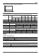
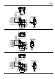
6. Wire leads left side type: Mounting hole 3mm, standard type
mm General tolerance: ±0.25
NOTES
1.9 dia.
8.4±0.2
5.4±0.15
C 0.3
R 0.5
R 0.5
TTP (5.9)
OP (NO) 8.4±0.3
OP (NC) 8.7±0.3
FP 9.2 MAX.
5.9
3.7
1.4 dia.
4.5
5.2
5.0±2
4.3
8.3±0.1
5.1
3.2±0.1
2.7
5.4
13.3
3.0
+0.1
−0
300±10 2.4
R 0.5
3.0
+0
−0.1
dia.
∗ Wire lead thickness
Wire lead color
:
:
:
:
0.3mm
2
COM
NC
NO
····
·······
·······
Black
Red
White
1. Soldering conditions
The application of excessive heat upon
the switch when soldering can cause
degradation of switch operation.
Therefore, be sure to keep within the
conditions given below.
1) Manual soldering: use soldering irons
(max. 350°C, within 3 seconds) capable
of temperature adjustment. This is to
prevent deterioration due to soldering
heat. Care should be taken not to apply
force to the terminals during soldering.
2) Automatic soldering: Soldering must
be done as below;
260°C: within 6 seconds
350°C: within 3 seconds
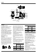
2. Mounting
Please avoid use in which load would be
applied to the sides (hatch part (both
sides) shown below) of the switch in the
direction indicated by the arrows. This
could cause erroneous operation. Also,
when using a metal installation board,
please make allowance for burr direction
designation and burr suppressing, etc.,
so that the burr side will not be on the
switch installation side.
1) To secure the switch, please use an
M3 small screw on a flat surface and
tighten using a maximum torque of 0.29
N·m. It is recommended that spring
washers be used with the screws and
adhesive be applied to lock the screws to
prevent loosening of the screws. Please
make sure not to apply adhesive onto the
moving parts.
2) Be sure to maintain adequate
insulating clearance between each
terminal and ground.
3) Although it is possible to directly
operate the pin plunger type from the
lateral direction, please consult us if
doing so.
4) After mounting please make sure no
tensile load will be applied to the switch
terminals.
5) Range of possible use: Please set the
operation position to within the ranges in
the following table so that there is
sufficient insulation distance and to
maintain contact reliability.
mm
6) PC board terminal type should be
used if the products are to be soldered on
the PC board. Solder terminal type is not
for soldering on PC board.
3. Cautions regarding the circuit
1) In order to prevent malfunction in set
devices caused by bounce and chattering
during the ON-OFF switch operation,
please verify the validity of the circuit
under actual operating conditions and
temperature range.
2) When switching inductive loads
(relays, solenoids, buzzers, etc.), an arc
absorbing circuit is recommended to
protect the contacts.
4. Please verify under actual
conditions.
Please be sure to conduct quality
verification under actual operating
conditions in order to increase reliability
during actual use.
5. Switch selection
Please make your selection so that there
will be no problems even if the operating
characteristics vary up to ±20% from the
standard values.
Actuator
Plunger/lever free
From mounting
boss and hole
center line
From standoff
Pin
plunger
>9.2 >13.4
Leaf lever >10.7 >14.9
Simulated
leaf lever
>13.5 >17.7
Actuator
Plunger/Lever pushed
From mounting
boss and hole
center line
From standoff
Pin
plunger
7.8 to 5.9 12.0 to 10.1
Leaf lever 8.4 to 6.2 12.6 to 10.4
Simulated
leaf lever
11.1 to 8.7 15.3 to 12.9
All Rights Reserved © COPYRIGHT Matsushita Electric Works, Ltd.