Operating Instructions Remote Camera Controller Model No.
Contents Before use ................................................................. 3 Setting the functions .............................................. 18 Overview ....................................................................................3 Setting the remote camera operations .....................................19 Trademarks and registered trademarks .....................................3 Setting the speed at which to move to the position set by the preset memory .......................
Before use Overview Disclaimer of warranty This unit is a controller which is designed to control remote cameras (cameras integrated with pan-tilt heads) and pan-tilt head systems (which consist of pan-tilt heads and the cameras which are mounted on them). By means of an IP connection, an operating environment where the unit is tied in with the AW-HE50 HD integrated camera and AW-HS50 compact live switcher is achieved.
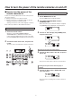
How to turn the power of the remote cameras on and off How to turn the power of the remote cameras on Turning on the power of a multiple number of cameras 1 Follow one of the procedures below to turn on the power of the remote cameras. Turning on the power one camera at a time Turning on the power of a multiple number of cameras • Turning on the power of all the cameras • Turning on the power of the selected group of cameras Press the MENU button to light its indicator.
How to turn the power of the remote cameras on and off How to turn the power of the remote cameras off Turning off the power of a multiple number of cameras 1 Follow one of the procedures below to turn off the power of the remote cameras. Turning off the power one camera at a time Turning off the power of a multiple number of cameras • Turning off the power of all the cameras • Turning off the power of the selected group of cameras Press the MENU button to light its indicator.
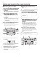
Setting and operating the preset memories This unit is provided with a function for registering the positions to be shot by the remote cameras and the settings of the remote cameras in the remote cameras themselves. Up to 100 sets of data (presets) can be registered in these memories. The positions and settings listed below can be registered.
Setting and operating the preset memories Deleting the preset memory data Executing the preset data 1 Press one of the CAMERA STATUS/SELECTION buttons 1 to 5 to select the remote camera to be operated. Note This function does not work with the AW-PH400. Select the remote camera which is to be pointed at the camera angle registered in the preset memory. 2 1 After pressing the PAGE button, press the PRESET MEMORY/MENU button to specify the registered “Page number” of the preset memory.
Selecting the settings for a selected remote camera Setting the pedestal The following settings and adjustments can be performed for a selected remote camera directly from this unit. • • • • • • Gain Pedestal R and B gain values R and B pedestal values White balance Black balance • • • • Perform the black level (pedestal) adjustment in order to make it easier to see the very dark parts of the images.
Selecting the settings for a selected remote camera Setting the white balance The modes which can be selected differ depending on the remote camera connected. The ratio between RGB (three primary colors) is adjusted so that white will be reproduced accurately. If the white balance is off, not only will white be reproduced poorly but the color tone of the entire picture will also deteriorate.
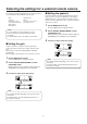
Selecting the settings for a selected remote camera When automatic adjustment is performed, the following details are displayed on the LCD panel. Automatically adjusting the white balance Set the automatic adjustment if the coloring appears unnatural under certain light sources or other conditions. If the white serving as the reference can be recognized, it is possible to shoot with natural coloring. AWB ACTIVE: This appears while AWB is being executed.
Selecting the settings for a selected remote camera Manually adjusting the white balance (Setting the R and B gain values) 1 2 3 Auto tracking white adjustment (ATW) This function provides compensation automatically so that the white balance is adjusted even when the light source or color temperature changes during shooting, so that images that appear the least odd (that is, the most natural looking) are produced. As with the automatic adjustment, fill the screen with a white subject.
Selecting the settings for a selected remote camera Setting the black balance The black balance must be adjusted when using a remote camera for the first time or when the remote camera has not been used for a prolonged period of time. It must also be adjusted when significant changes have occurred in the ambient temperature or at the change of the seasons. If the camera is used with the same settings and under the same conditions, the black balance need not be adjusted again.
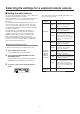
Selecting the settings for a selected remote camera Setting the shutter speed Setting the detail The shutter mode and shutter speed of the remote camera can be selected. The image detail (image sharpness) can be adjusted. 1 1 Set the MENU button to ON. Press the MENU button to light its indicator. Press the MENU button to light its indicator. 2 2 Set the PRESET MEMORY/MENU 5 button (SHUTTER) to ON. Turn the F1 dial to select the shutter mode.
Selecting the settings for a selected remote camera Setting the shooting mode Specifying the color bars Select the shooting mode that matches the shooting conditions. Select the mode according to the shooting conditions and your preferences. The images to be output from the remote camera can be switched between the “camera images” and “color bars”. 1 1 Press the MENU button to light its indicator. Set the MENU button to ON. 2 Press the MENU button to light its indicator.
Operating the menu items of the selected remote camera The menu operations of the remote cameras can be operated from the unit for the remote camera which is now selected. The CAMERA OSD button, F1 dial and F2 dial are used to perform the operations. When the CAMERA OSD button is held down, its indicator lights, and the on-screen menu of the selected remote camera is displayed as the output image of the remote camera.
Setting the USER buttons Registering functions in the USER buttons Menu items can be assigned to the two USER buttons (USER1, USER2). The target function can be activated simply by pressing the USER button (USER1 or USER2). 1 Set the MENU button to ON. Press the MENU button to light its indicator.
Tally settings Set enable (On) or disable (Off) for tally ON which provides the tally instructions to the remote camera in response to tally requests received via the GPI and network. 1 Set the MENU button to ON. Press the MENU button to light its indicator. 2 Set PRESET MEMORY/MENU 8 button (CAMERA) to ON. When the button is pressed and its indicator is lighted, the [CAMERA] menu is displayed on the LCD panel. [1] G R O U P 3 ▼ Turn the F1 dial to display the [TALLY] menu, and press the F1 dial.
Setting the functions 4 This section describes how the unit’s functions are set. The following functions can be set. Turn the F1 dial to select the target menu item. 1.
Setting the functions Setting the remote camera operations Setting the zooming direction Set these operations by selecting the [SETUP] menu followed by the [OPERATE] menu. From the [SETUP] menu, select [OPERATE] and display [ZOOM DIR].Then select either “NORMAL” or “REVERSE”. [4] O P E R A T E 3.ZOOM DIR NORMAL Setting the pan, tilt, zoom and focus operation directions This sets the zooming operation of the lens in response to the operation of the ZOOM button.
Setting the functions Switching from focus control to iris control or vice versa Settings when the remote camera moves horizontally or vertically during tele shooting It is possible to switch the control, which is implemented by dial and button operations, from focus control to iris control (or vice versa). During tele shooting, the remote camera’s pan/tilt operation are slowed down to make positioning easier. Note 1 IRIS This function takes effect when the unit is connected to the AW-HE50.
Setting the functions Returning the remote cameras to their home position Setting the speed at which to move to the position set by the preset memory The remote cameras connected can be returned to their home position. The speed at which to move to the position where the remote camera has been set to be in the preset memory when the preset operation is conducted can be set. From the [SETUP] menu, select [PRESET] and display [HOME POSITION]. Then press the F2 dial.
Setting the functions Setting the movement range of the remote camera (limiter function) This unit has a limiter function which is a function that limits the movement range of the remote cameras. There are four limiter positions: the upper, lower, left and right limits of the movement range. Display that appears with other remote cameras The setting status is displayed after the completion of the setting in the LIMIT UP item. When the AW-HE50 is used: 2.
Setting the functions Setting the left limit Setting the right limit From the [SETUP] menu, select [PTZ ADJ] and display [LIMIT LEFT]. Then set the left limit. From the [SETUP] menu, select [PTZ ADJ] and display [LIMIT RIGHT]. Then set the right limit. The setting that is displayed differs between the AW-HE50 and other remote cameras. The setting that is displayed differs between the AW-HE50 and other remote cameras.
Setting the functions Controlling the peripheral devices connected to the remote cameras When any of the peripheral devices listed below are connected to the remote cameras, they can be controlled. • ND filter • AC adapter (AW-PS300A) • Defroster Controlling a wiper • Wiper • Heater, fan • Halogen lamp This item is used to control a wiper when using a remote camera (AW-PH650 + camera) equipped with a wiper function as the currently selected remote camera.
Setting the functions Adjusting the minimum lens zoom start speed Exercising external control over the preset memory data This adjustment ensures that the lens zoom will start moving smoothly in line with the inclination of the ZOOM button when operating the lens zoom using the ZOOM button. Preset numbers can be assigned to execute presets for the selected remote cameras when signals have been input to the TALLY/GPI input/output connector.
Setting the functions Adjusting the LCD panel backlight Locking the button operations This disables the operation of the CAMERA OSD button and PRESET MEMORY/MENU buttons (1 to 7). The backlight of the LCD panel can be adjusted. The button operations are locked using the MENU CTL item of the [SETUP] menu. [10 ] M E N U C T L Make this adjustment using the LCD BL item on the [SETUP] menu.
Setting linkup with the switcher 4 This setting is used to link the unit with an optional switcher (AW-HS50). To link the unit with the switcher, the following settings must be established in the unit. IP address (switcher) setting [SYSTEM] menu [SW IP ADR] Assign information setting [SYSTEM] menu [SW CTL] Link connection setting [SETUP] menu [SW LINK] [SWLINK] Settings at the switcher For details on the settings selected at the switcher, refer to the Operating Instructions of the switcher.
Setting linkup with the switcher Link setting 1 Set the MENU button to ON. Press the MENU button to light its indicator. 2 Set PRESET MEMORY/MENU 9 button (SETUP) to ON. When the button is pressed and its indicator is lighted, the [SETUP] menu is displayed on the LCD panel. [1] U S E R 3 ▼ Turn the F1 dial, display the SW LINK menu, and press the F1 dial. [2] S W L I N K Press the F1 dial. 1.S W L I N K ▼ Off 4 Turn the F2 dial to select On, and then press the F2 dial to change the setting. 1.
Setting the functions when the unit is linked with the switcher 5 Set the various functions to be used when the unit is linked with the switcher. Setting the image output and image input 2.INPUT2 CAM1 Turn the F2 dial, and then press it. This setting establishes the correlation between the image output (remote camera) and image input (switcher).
Setting the functions when the unit is linked with the switcher 5 Switcher settings A setting for controlling the switcher linked with the unit is available. It is established using the [SETUP] menu. Before taking the steps described here, the steps for “Switcher network settings” and “Setting the image output and image input” must be taken. Turn the F2 dial, select the settings, and then press the F2 dial to change the setting. 2.BUSCONT Off Turn the F2 dial, and then press it. 2.
Setting the functions when the unit is linked with the switcher Bus setting Camera information setting From the [SETUP] menu, select [SW LINK] and display [BUS]. Then set the material (AUX, PVW, PinP or KEY) to be sent to the switcher. From the [SETUP] menu, select [SW LINK] and display [CAMSEL]. Then set On or Off. 5.CAMSEL 3 .
Setting the functions when the unit is linked with the switcher The following tally-related settings can be established using the menu. OA tally setting From the [SETUP] menu, select [SW LINK] and display [TALLY_IP]. Then set On or Off. Enabling/disabling the tally information instructions sent over the network If only the tally information from GPI is to be enabled, from the [SETUP] menu select [SW LINK], set [TALLY_IP] to Off, and disable the tally information instructions sent over the network. 6 .
Setting the functions when the unit is linked with the switcher 5 Setting for the information to be displayed on the OSD 2.FORMAT This setting displays the remote camera information on the OSD of the monitor which is connected to the switcher to be linked to the unit. Off Turn the F2 dial, and then press it. The setting is established using the [SETUP] menu.
Setting the functions when the unit is linked with the switcher Setting each information item to be displayed Iris value From the [SETUP] menu, select [SW DISP] and display [IRIS]. Then set On or Off. Video format 7.IRIS From the [SETUP] menu, select [SW DISP] and display [FORMAT]. Then set On or Off. Off 2.FORMAT Off Filter information From the [SETUP] menu, select [SW DISP] and display [FILTER]. Then set On or Off. Remote camera name 8.
Checking the equipment alarm information It is possible to check the alarm statuses of the unit and the remote cameras assigned to the CAMERA STATUS/ SELECTION buttons. 1 [Select POWER] The unit’s power supply alarm can be checked. No ALARM: When the power supply is trouble-free. ALARM: When trouble has occurred in the power supply. Set the MENU button to ON. Press the MENU button to light its indicator. 2 [Select CAM1 to CAM100] Set PRESET MEMORY/MENU 10 button (SYSTEM) to ON.
Returning the unit to its factory status The unit’s settings can be returned to the factory statuses. Two methods can be used: One method returns all the settings to the factory statuses, and the other returns only the [SETUP] menu settings to the factory statuses. 1 4 Turn the F2 dial to select the initializing mode. 1.INITIALIZE ALL Set the MENU button to ON. Turn the F2 dial. Press the MENU button to light its indicator. 2 1.INITIALIZE SETUP Set PRESET MEMORY/MENU 10 button (SYSTEM) to ON.
Control interface for external devices TALLY/GPI TALLY IN 1 to TALLY IN 5 are contact input ports which are used to light the unit’s tally indicators (above the CAMERA STATUS/SELECTION buttons). The tally lamps light with contact input. GPI IN 1 to GPI IN 4 are contact input ports which are used to control the unit from an external source. GPI OUT 1 to GPI OUT 4 are open output ports which are used to output the statuses to an external source. Pin No.
Setup Software The “Setup Software” is an application which enables the same functions as the unit’s automatic IP settings to be executed from the host computer. This is used to set the network environment for operating the remote camera using the host computer. It can save the setting data files in the host computer, and it can load the saved files and reflect them in the network environment. For details, refer to the sections that follow.
Setup Software Displaying the “Setting” tab List box SW Input The IP address of the AW-RP50 connected to the network is displayed here. The information of the network environment established by the AW-RP50 selected here is displayed on the “Setting” tab. The input connectors of the switcher are displayed in this column. The input connector can be changed manually. Click on the right, and select “NoAsign” or an input connector from “INPUT1” to “INPUT5.
Setup Software Auto IP setting Changing the camera numbers The camera numbers set for the remote cameras can be changed. When IP addresses are to be changed 1 1 Click [RENEW]. New IP addresses are set in the target remote cameras and switcher. When [CANCEL] is clicked, the original settings are restored.
Setup Software Saving and loading data On the “File Operate” tab screen, the files with the network environment settings are saved and loaded. Loading the setting files Load the files with the network environment setting data. (Filename: .r50) 1 Click [File], and specify the setting file to be loaded. The name of the selected file is displayed in the text box. It is also possible to input the filename directly. 2 Click [Load].
Setup Software Referencing the network environment On the “IP Address” tab, it is possible to select the IP addresses of the other AW-RP50 remote camera controllers which have been connected in the network. The information of the network environment created by the selected AW-RP50 units can be referenced using the “Setting” tab. Up to five AW-RP50 units can be selected. 1 Enter the IP addresses in the AW-RP50 IP ADDRESS boxes.
Table of menu items Button 1 GAIN/PED GAIN Menu item Control device AW-HE50 AW-HE100 AW-HE870 AW-E860, AW-E750, AW-E650, AW-E350 AK-HC1500, AK-HC1800 PEDESTAL 2 R/BGAIN RGAIN BGAIN 3 R/BPED RPED BPED 4 AWB/ABB AWB SEL AW-HE50 AW-HE100 AW-HE870 AW-E860, AW-E750, AW-E650, AW-E350 AK-HC1500, AK-HC1800 AW-HE50 AW-HE100 AW-HE870 AW-E860, AW-E750, AW-E650, AW-E350 AK-HC1500, AK-HC1800 AW-HE50 AW-HE100 AW-HE870 AW-E860, AW-E750, AW-E650, AW-E350 AK-HC1500, AK-HC1800 AW-HE50 AW-HE100 AW-HE870 AW-E860, A
Table of menu items Button 5 SHUTTER Menu item SHUTTER SPEED Control device AW-HE50 AW-HE100 AW-HE870 AW-E860, AW-E750, AW-E650, AW-E350 AK-HC1500, AK-HC1800 AW-HE50 Initial value Off, Off, Off, Off, AW-HE870 AW-E860, AW-E750, AW-E650, AW-E350 AK-HC1500, AK-HC1800 7 SCENE/ MODE DETAIL LEVEL FILME: 180.0, 172.8, 144.0, 120.0, 90.0, 45.
Table of menu items Button 9 SETUP [1]USER [2]SW LINK [3]SW DISP [4]OPERATE [5]PRESET Menu item 1.USER1 Control device Initial value AWB 2.USER2 ABB 1.SWLINK 2.BUSCONT 3.BUS 4.FASIST 5.CAMSEL 6.TALLY_IP 7.P/T LEVER 1.CAMINF 2.FORMAT 3.CAMNAME 4.SCENE 5.GAIN 6.SHUTTER 7.IRIS 8.FILTER 9.ALARM 1.PAN DIR 2.TILT DIR 3.ZOOM DIR 4.FOCUS DIR 5.SPEED WITH Z AW-HE50 AW-HE100 AW-PH360, AW-PH405, 6.SPEED TARGET 7.FOCUS/IRIS 8.P/T CURV 1.DIAG SPEED AW-HE50 AW-HE100 AW-PH360, AW-PH405, 2.
Table of menu items Button 9 SETUP Menu item [6]FUNCTION 1.ND FILTER 2.OPTION 3.DEFROSTER 4.WIPER 5.HEATER/FAN 6.LAMP [7]PTZ ADJ 1.Z MIN SPEED 2.LIMIT UP 3.LIMIT DOWN 4.LIMIT LEFT 5.
Table of menu items Button 10 SYSTEM Menu item [1]CAMERA CTL 1.CAM1 to 100.CAM100 [2]CAM ASSIGN 1.CAM1 to 100.CAM100 [3]SW CTL 1.SW [4]SW ASSIGN 1.INPUT1 2.INPUT2 3.INPUT3 4.INPUT4 5.INPUT5 [5]AUTO SET IP 1.AUTO SETUP Control device Initial value NoAsign Setting Serial, Network, NoAsign 192.168.000.010 NoAsign Network, NoAsign CAM1 CAM2 CAM3 NoAsign, CAM1 to 100 CAM4 CAM5 RENEW IP ADR RENEW IP ADR, KEEP IP ADR, ALL CLEAR 192.168.000.009 255.255.255.000 192.168.000.001 Display only 192.168.000.
© Panasonic System Networks Co., Ltd.