Operating Instructions Remote Camera Controller Model No.
Contents Setting the functions .............................................. 17 Before use ................................................................. 3 Setting the remote camera operations .....................................18 Overview ....................................................................................3 Setting the speed at which to move to the position set by the preset memory .....................................................................
Before use w Overview w Disclaimer This unit is a controller which is designed to control remote cameras (cameras integrated with pan-tilt heads) and pantilt head systems (which consist of pan-tilt heads and the cameras which are mounted on them). By means of an IP connection, an operating environment where the unit is tied in with the AW-HE50 HD integrated camera and AW-HS50 compact live switcher is achieved. When IP connections are used, the unit can be used to control up to 100 cameras.
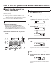
How to turn the power of the remote cameras on and off w How to turn the power of the remote cameras on Turning on the power of a multiple number of cameras 1 Follow one of the procedures below to turn on the power of the remote cameras. p Turning on the power one camera at a time p Turning on the power of a multiple number of cameras Turning on the power of all the cameras Turning on the power of the selected group of cameras Press the MENU button to light its indicator.
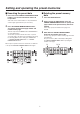
Setting and operating the preset memories To register more data, repeat steps 2 to 5. This unit has a preset memory function for registering the preset data of the shooting positions and settings of the remote cameras. Up to 100 sets of data (presets) can be registered in these memories. p When specifying a different “number on the page” on the same “page number,” it is registered by skipping step 4 and carrying out the operation in step 5 only.
Setting and operating the preset memories w Deleting the preset memory data w Executing the preset data 1 2 Press one of the CAMERA STATUS/SELECTION buttons 1 to 5 to select the remote camera to be operated. 1 Select the remote camera which is to be pointed at the camera angle registered in the preset memory. 2 Press the PRESET MEMORY/MENU button, and specify the registered page number and number on the page. Press the DELETE button.
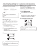
Selecting the settings for a selected remote camera w Setting the pedestal The following settings and adjustments can be performed for a selected remote camera directly from this unit. • • • • • Gain Pedestal R and B gain values White balance Black balance • • • • Perform the black level (pedestal) adjustment in order to make it easier to see the very dark parts of the images.
Selecting the settings for a selected remote camera w Setting the R and B gain values w Setting the R and B pedestal Adjust the amounts by which the R gain and B gain values are to be incremented or decremented using the G gain value obtained when the white balance has been adjusted as the reference. When auto white balance is performed, the adjustment value is set to “000”.
Selecting the settings for a selected remote camera w Setting the white balance The modes which can be selected differ depending on the remote camera connected. The ratio between RGB (three primary colors) is adjusted so that white will be reproduced accurately. If the white balance is off, not only will white be reproduced poorly but the color tone of the entire picture will also deteriorate.
Selecting the settings for a selected remote camera 4 Automatically adjusting the white balance Turn the F2 dial to select AWB, and press the F2 dial. Set the automatic adjustment if the coloring appears unnatural under certain light sources or other conditions. If the white serving as the reference can be recognized, it is possible to shoot with natural coloring. The remote camera now automatically adjusts the white balance, and registers it at the place selected in step 3.
Selecting the settings for a selected remote camera Manually adjusting the white balance 1 2 3 Automatic color temperature tracking (ATW) As with the automatic adjustment, fill the screen with a white subject. This function provides compensation automatically so that the white balance is adjusted even when the light source or color temperature changes during shooting, so that images that appear the least odd (that is, the most natural looking) are produced.
Selecting the settings for a selected remote camera w Setting the black balance Manually adjusting the black balance The black balance must be adjusted when using a remote camera for the first time or when the remote camera has not been used for a prolonged period of time. It must also be adjusted when significant changes have occurred in the ambient temperature or at the change of the seasons.
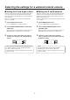
Selecting the settings for a selected remote camera w Setting the shutter speed w Setting the detail The shutter mode and shutter speed of the remote camera can be selected. The image detail (image sharpness) can be adjusted. 1 1 Set the MENU button to ON. Press the MENU button to light its indicator. Press the MENU button to light its indicator. 2 2 Set the PRESET MEMORY/MENU 5 button (SHUTTER) to ON. 3 Set the PRESET MEMORY/MENU 6 button (DETAIL) to ON.
Selecting the settings for a selected remote camera w Setting the shooting mode w Specifying the color bars Select the shooting mode that matches the shooting conditions. Select the mode according to the shooting conditions and your preferences. The images to be output from the remote camera can be switched between the “camera images” and “color bars”. 1 1 Press the MENU button to light its indicator. Set the MENU button to ON. 2 Press the MENU button to light its indicator.
Operating the menu items of the selected remote camera The menu operations of the remote cameras can be operated from the unit for the remote camera which is now selected. The CAMERA OSD button, F1 dial and F2 dial are used to perform the operations. F1 F2 POWER ALARM MENU PAGE Note The operations differ depending on the remote camera model. For details on the menu items which are displayed, check the operating instructions of the model concerned.
Setting the USER buttons w Registering functions in the USER buttons Menu items can be assigned to the two USER buttons (USER1, USER2). After assigning an item, the assigned menu item can be displayed simply by pressing one of these USER buttons (USER1 or USER2). 1 Set the MENU button to ON. Press the MENU button to light its indicator.
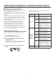
Setting the functions 4 This section describes how the unit’s functions are set. The following functions can be set. 1.PAN DIR p Setting of the remote camera operations p Registration of functions in the USER buttons p Setting the speed at which to move to the preset memory setting position p Setting the control items used when preset data is executed p Controlling the peripheral devices connected to the remote cameras • ND filter • AC adapter (AW-PS300A) • Defroster Turn the F1 dial. 2.
Setting the functions w Setting the remote camera operations Setting the zooming direction Set these operations by selecting the [SETUP] menu followed by the [OPERATE] menu. From the [SETUP] menu, select [OPERATE] and display [ZOOM DIR].Then select either “NORMAL” or “REVERSE”. [4] O P E R A T E 3.ZOOM DIR NORMAL q Setting the pan, tilt, zoom and focus operation directions This sets the zooming operation of the lens in response to the operation of the ZOOM button.
Setting the functions q Selecting the control items (pan, tilt, zoom and focus) q Settings when the remote camera moves horizontally or vertically during tele shooting Select the control items for the currently selected remote camera. During tele shooting, the remote camera’s pan/tilt operation are slowed down to make positioning easier. From the [SETUP] menu, select [OPERATE] and display [SPEED TARGET]. Then select the control item. From the [SETUP] menu, select [OPERATE] and display [SPEED WITH Z].
Setting the functions q Switching from focus control to iris control or vice versa q Setting the PAN/TILT lever inclination and speed It is possible to switch the control, which is implemented by dial and button operations, from focus control to iris control (or vice versa). The correlation between angle and operating speed when the PAN/TILT lever is inclined can be adjusted. 1 IRIS AUTO 2 3 4 From the [SETUP] menu, select [OPERATE] and display [P/T CURV].
Setting the functions w Adjusting the panning, tilting, zooming and focusing speed w Setting the speed at which to move to the position set by the preset memory The speed is adjusted uniformly for the panning, tilting, zooming and focusing together. The speed at which to move to the position where the remote camera has been set to be in the preset memory when the preset operation is conducted can be set.
Setting the functions q Setting the lower limit w Setting the movement range of the remote camera (limiter function) From the [SETUP] menu, select [PTZ ADJ] and display [LIMIT DOWN]. Then set the lower limit. The setting that is displayed differs between the AW-HE50 and other remote cameras. This unit has a limiter function which is a function that limits the movement range of the remote cameras.
Setting the functions q Setting the left limit q Setting the right limit From the [SETUP] menu, select [PTZ ADJ] and display [LIMIT LEFT]. Then set the left limit. From the [SETUP] menu, select [PTZ ADJ] and display [LIMIT RIGHT]. Then set the right limit. The setting that is displayed differs between the AW-HE50 and other remote cameras. The setting that is displayed differs between the AW-HE50 and other remote cameras.
Setting the functions w Returning the remote cameras to their home position The remote cameras connected can be returned to their home position. From the [SETUP] menu, select [PRESET] and display [HOME POSITION]. Then press the F2 dial. 3 .
Setting the functions w Controlling the peripheral devices connected to the remote cameras Controlling a wiper This item is used to control a wiper when using a remote camera (AW-PH650) equipped with a wiper function as the currently selected remote camera. From the [SETUP] menu, select [FUNCTION] and display [WIPER]. Then select wiper On or Off. When any of the peripheral devices listed below are connected to the remote cameras, they can be controlled.
Setting the functions w Adjusting the minimum pan/tilt start speed w Adjusting the minimum lens zoom start speed The minimum speed at which the pan-tilt head is to start moving is automatically adjusted to ensure that the remote camera will start moving smoothly in line with the inclination of the PAN/TILT lever when manually operating the pan-tilt head using the joystick. This adjustment enables the play in the PAN/TILT lever to be reduced.
Setting the functions w Locking the button operations w Assigning preset data when emergency interrupts occur This disables the operation of the CAMERA OSD button, and PRESET MEMORY/MENU buttons (1 to 7). Preset numbers can be assigned to execute presets for all the connected remote cameras when signals have been input to the TALLY/GPI input/output connector. The button operations are locked using the MENU CTL item of the [SETUP] menu. The presets are assigned using the GPI item on the [SETUP] menu.
Linking the unit with the switcher This setting is used to link the unit with an optional switcher (AW-HS50). w Switcher network settings 1 Set the MENU button to ON. Press the MENU button to light its indicator. 2 Set PRESET MEMORY/MENU 10 button (SYSTEM) to ON. When the button is pressed and its indicator is lighted, the [SYSTEM] menu is displayed on the LCD panel. [ 1 ]C A M E R A C T L 3 ▼ Turn the F1 dial, display the SW IP ADR menu, and press the F1 dial. [ 7] SW IP ADR Press the F1 dial.
Linking the unit with the switcher 5 w Setting the image output and image input 2.INPUT2 This setting establishes the correlation between the image output (remote camera) and image input (switcher). By establishing the setting, the switcher is notified if a remote camera which has been set is selected when the remote cameras have been selected by the unit. 1 Turn the F2 dial, select the remote camera, and then press the F2 dial to enter the selection. CAM1 Turn the F2 dial, and then press it. 2.
Linking the unit with the switcher 5 w Switcher settings Turn the F2 dial, select the settings, and then press the F2 dial to change the setting. A setting for controlling the switcher linked with the unit is available. It is established using the [SETUP] menu. Before taking the steps described here, the steps for “Switcher network settings” and “Setting the image output and image input” must be taken. 2.BUSCONT Off Turn the F2 dial, and then press it. 2.
Linking the unit with the switcher Bus setting Camera information setting From the [SETUP] menu, select [SW LINK] and display [BUS]. Then set the material (AUX, PVW, PinP or KEY) to be sent to the switcher. From the [SETUP] menu, select [SW LINK] and display [CAMSEL]. Then set On or Off. 5.CAMSEL 3.BUS Off AUX When “On” is selected as the item setting, an icon appears at the bottom left of the image of the remote camera selected by the unit on the switcher’s multi view display.
Linking the unit with the switcher OA tally setting The following tally-related settings can be established using the menu. From the [SETUP] menu, select [SW LINK] and display [TALLY_IP].Then set On or Off. 6.TALLY_IP p Enabling/disabling the tally information instructions sent over the network If only the tally information from GPI is to be enabled, from the [SETUP] menu select [SW LINK], set [TALLY-IP] to Off, and disable the tally information instructions sent over the network.
Linking the unit with the switcher 5 w Setting for the information to be displayed on the OSD 2.FORMAT This setting displays the remote camera information on the OSD of the monitor which is connected to the switcher to be linked to the unit. Off Turn the F2 dial, and then press it. The setting is established using the [SETUP] menu. Before taking the steps here, the steps for “Switcher network settings” and “Setting the image output and image input” described earlier must be taken. 2.
Linking the unit with the switcher q Setting each information item to be displayed Iris value From the [SETUP] menu, select [SW DISP] and display [IRIS]. Then set On or Off. Video format 7.IRIS From the [SETUP] menu, select [SW DISP] and display [FORMAT]. Then set On or Off. Off 2 . FO R M A T Off Filter information From the [SETUP] menu, select [SW DISP] and display [FILTER]. Then set On or Off. Remote camera name 8.FILTER From the [SETUP] menu, select [SW DISP] and display [CAMNAME].
Checking the equipment alarm information 4 It is possible to check the alarm statuses of the unit and the remote cameras assigned to the CAMERA STATUS/ SELECTION buttons. 1 The target device is displayed at the top, and the alarm status is displayed underneath. Set the MENU button to ON. 1.POWER Press the MENU button to light its indicator. 2 ▼ NO ALARM Set PRESET MEMORY/MENU 10 button (SYSTEM) to ON. Turn the F2 dial.
Returning the unit to its factory status The unit’s settings can be returned to the factory statuses. Two methods can be used: One method returns all the settings to the factory statuses, and the other returns only the [SETUP] menu settings to the factory statuses. 1 Set the MENU button to ON. Press the MENU button to light its indicator. 2 Set PRESET MEMORY/MENU 10 button (SYSTEM) to ON. When the button is pressed and its indicator is lighted, the [SYSTEM] menu is displayed on the LCD panel.
Control interface for external devices w TALLY/GPI TALLY1 to TALLY4 are contact input ports which are used to light the unit’s TALLY indicators. The TALLY lamps light with contact input. GPI_In1 to GPI_In4 are contact input ports which are used to control the unit from an external source. GPI_Out1 to GPI_Out4 are open output ports which are used to output the statuses to an external source. Pin No.
RP setting tool w Installing the software Be absolutely sure to read through the “Readme.txt” on the CD-ROM supplied with the unit first before attempting to install the software. Software provided on the CD-ROM p RP50PCTOOL This is used to set the network environment for operating the remote camera using the host computer. It can save the setting data files in the host computer, and it can load the saved files and reflect them in the network environment. For details, refer to the sections that follow.
RP setting tool q Auto IP setting q Changing the camera numbers The camera numbers set for the remote cameras can be changed. When IP addresses are to be changed 1 1 Click [RENEW]. New IP addresses are set in the target remote cameras and switcher. p When [CANCEL] is clicked, the original settings are restored. 2 2 q Registering the camera numbers in the switcher’s input connectors Set the camera numbers to be registered for the input connectors (SDI IN 1 to SDI IN 4, DVI IN) of the switcher.
RP setting tool q Alarm displays The alarms of the remote cameras (5 units) are displayed in the [Alarm] field. They are displayed for the remote cameras in the currently selected group. For remote cameras with a serial connection, they are displayed only when the cameras are selected. q Displaying the camera names The names set for the remote cameras (5 units) are displayed. They are displayed for the remote cameras in the currently selected group.
RP setting tool w Saving and loading data On the “File Operate” tab screen, the files with the network environment settings are saved and loaded. q Saving the setting files Save the files with the network environment setting data. (Filename: @@@.r50) 1 2 In the section, click [Save] under “From AW-RP50”. Input the filename, and click [Save]. When the file has been saved, the following message is displayed. The file save screen now appears.
RP setting tool q Loading the setting files q Saving the log files Load the files with the network environment setting data. (Filename: @@@.r50) Save the log files. (Filename: RP50.log) 1 1 Click [File]. The file selection screen now appears. In the section, click [Save] under “From AW-RP50”. The file save screen now appears. 2 Select the file, and click [Open]. 2 The filename is displayed under “To AW-RP50”. 3 Input the filename, and click [Save].
Table of menu items Button 1 GAIN/PED Menu item GAIN Control device AW-HE50 AW-HE100 AW-HE870 AW-E860, AW-E750, AW-E650, AW-E350 AK-HC1500, AK-HC1800 PEDESTAL 2 R/BGAIN RGAIN BGAIN 3 R/BPED RPED BPED 4 AWB/ABB AWB SEL AW-HE50 AW-HE100 AW-HE870 AW-E860, AW-E750, AW-E650, AW-E350 AK-HC1500, AK-HC1800 AW-HE50 AW-HE100 AW-HE870 AW-E860, AW-E750, AW-E650, AW-E350 AK-HC1500, AK-HC1800 AW-HE50 AW-HE100 AW-HE870 AW-E860, AW-E750, AW-E650, AW-E350 AK-HC1500, AK-HC1800 AW-HE50 AW-HE100 AW-HE870 AW-E860, A
Table of menu items Button 5 SHUTTER Menu item SHUTTER SPEED Control device AW-HE50 AW-HE100 AW-HE870 AW-E860, AW-E750, AW-E650, AW-E350 AK-HC1500, AK-HC1800 AW-HE50 Initial value Off, Off, Off, Off, AW-HE870 AW-E860, AW-E750, AW-E650, AW-E350 AK-HC1500, AK-HC1800 DETAIL LEVEL FILME: 180.0, 172.8, 144.0, 120.0, 90.0, 45.
Table of menu items Button 9 SETUP USER SW LINK SW DISP OPERATE Menu item USER1 Control device USER2 ABB SWLINK BUSCONT BUS FASIST CAMSEL TALLY_IP P/T LEVER CAMINF FORMAT CAMNAME SCENE GAIN SHUTTER IRIS FILTER ALARM PAN DIR TILT DIR ZOOM DIR FOCUS DIR SPEED WITH Z Off Off AUX Off Off Off AW-HE50 AW-HE100 AW-PH360, AW-PH400, AW-PH405, AW-PH650 SPEED TARGET FOCUS/IRIS PRESET FUNCTION Initial value AWB P/T CURV DIAG SPEED SCOPE HOME POSITION ND FILTER Off Off Off Off Off Off Off Off Off NORMA
Table of menu items Button 9 SETUP PTZ ADJ Menu item P/T MIN SPEED Z MIN SPEED LIMIT UP LIMIT DOWN LIMIT LEFT LIMIT RIGHT Control device AW-HE50 AW-HE100 AW-PH360, AW-PH405, AW-HE50 AW-HE100 AW-PH360, AW-PH405, AW-HE50 AW-HE100 AW-PH360, AW-PH405, AW-HE50 AW-HE100 AW-PH360, AW-PH405, AW-PH400, AW-PH650 AW-PH400, AW-PH650 AW-PH400, AW-PH650 AW-PH400, AW-PH650 Off EXEC EXEC Off EXEC EXEC Off, On EXEC EXEC Off EXEC EXEC Off, On EXEC EXEC Off EXEC EXEC Off, On EXEC EXEC On DISABLE NoAsign REN
© Panasonic System Networks Co., Ltd.
Operating Instructions Remote Camera Controller Model No. AW-RP50N Before operating this product, please read the instructions carefully and save this manual for future use.
Safety precautions CAUTION: CAUTION TO REDUCE THE RISK OF FIRE OR SHOCK HAZARD AND ANNOYING INTERFERENCE, USE THE RECOMMENDED ACCESSORIES ONLY. RISK OF ELECTRIC SHOCK DO NOT OPEN CAUTION: TO REDUCE THE RISK OF ELECTRIC SHOCK, DO NOT REMOVE COVER (OR BACK). NO USER SERVICEABLE PARTS INSIDE. REFER TO SERVICING TO QUALIFIED SERVICE PERSONNEL. FCC Note: This equipment has been tested and found to comply with the limits for a class A digital device, pursuant to Part 15 of the FCC Rules.
Safety precautions IMPORTANT SAFETY INSTRUCTIONS Read these operating instructions carefully before using the unit. Follow the safety instructions on the unit and the applicable safety instructions listed below. Keep these operating instructions handy for future reference. 10) Protect the power cord form being walked on or pinched particularly at plugs, convenience receptacles, and the point where they exit from the apparatus. 1) Read these instructions. 2) Keep these instructions. 3) Heed all warnings.
Contents Connections ......................................................................19 Before use ...........................................................................5 Example of IP connections ............................................19 Overview ..........................................................................5 Example of serial connections .......................................20 Concerning the Operating Instructions ............................
Before use w Overview w Disclaimer This unit is a controller which is designed to control remote cameras (cameras integrated with pan-tilt heads) and pantilt head systems (which consist of pan-tilt heads and the cameras which are mounted on them). By means of an IP connection, an operating environment where the unit is tied in with the AW-HE50 HD integrated camera and AW-HS50 compact live switcher is achieved. When IP connections are used, the unit can be used to control up to 100 cameras.
Characteristics Compact design p The unit features a compact design with its half-rack size width (210 mm (8-1/4˝)) and its 4RU size (177 mm (6-15/16˝)) depth. The unit is the same size as the AW-HS50 compact live switcher (option), and when the switcher is placed alongside the unit, the two units are neatly housed in the full rack width.
Pan-tilt heads and cameras supported w Remote cameras supported (cameras integrated with a pan-tilt head) AW-HE100, AW-HE50 w Pan-tilt heads supported AW-PH360, AW-PH405, AW-PH650, AW-PH400 (AW-IF400 required) w Cameras supported (must be combined with the pan-tilt head supported) AW-HE870, AW-E860, AW-E750, AW-E650, AW-E350, AK-HC1500, AK-HC1800 Notes p Prior to use, be absolutely sure to set the movement ranges (limiters).
Required personal computer environment Run the software that is provided with the switcher on a host computer which satisfies the following specifications. CPU Intel® CoreTM2 DUO 2.
Installation precautions q In addition to heeding the points presented in the “Safety precautions”, observe the following precautions as well. Be absolutely sure to ask your dealer to do the jobs of installing and connecting the unit. Connecting the power supply Handle carefully! p Use within AC 100 V to 120 V. p Be absolutely sure to use only the power cord and AC adapter supplied with the panel. p Be absolutely sure to connect the grounding terminal of the power cord to ground.
Operating precautions Handle carefully. Do not drop the product, or subject it to strong shock or vibration. Do not carry or move the product by the PAN/TILT lever. This is important to prevent trouble. When the product is to be discarded When the product is to be discarded at the end of its service life, ask a specialized contractor to dispose of it properly in order to protect the environment. Concerning the consumable parts p AC adapter: This is a consumable part.
Parts and their functions w Control panel F1 F2 POWER ALARM MENU PAGE STORE DELETE IRIS AUTO 1 2 3 4 5 GAIN/PED R/B GAIN R/B PED AWB/ABB SHUTTER 6 7 8 9 10 DETAIL SETUP SCENE/MODE CAMERA PRESET MEMORY / MENU 1 2 3 4 SYSTEM F1 CAMERA OSD F2 EXIT USER1 USER2 5 PT ACTIVE CAMERA STATUS / SELECTION AUTO TELE ZOOM WIDE LOW HI PTZ/FOCUS SPEED FOCUS/PUSH OAF POWER indicator [POWER] PAN/TILT F1 dial, F2 dial These dials are turne
Parts and their functions DELETE button [DELETE] CAMERA OSD button [CAMERA OSD] When the CAMERA OSD button is held down, its indicator lights, and the on-screen menu of the selected remote camera is displayed as the output image of the remote camera. When the button is held down again while its indicator is lighted, the menu is cleared, and the indicator goes off. Press this to delete the preset memory data for the currently selected remote camera.
Parts and their functions Auto focus button [AUTO] PTZ/FOCUS SPEED dial [PTZ/FOCUS SPEED] Press this to control the focus automatically. Button indicator ON: Auto focusing Button indicator OFF: Manual focusing During auto focusing, operating the FOCUS/PUSH OAF dial ( ) will have no effect. Use this dial to adjust the speed at which the operations (pan, tilt, zoom, focus) of the remote cameras are controlled.
Parts and their functions w Rear panel " SIGNAL GND ON TALLY/GPI 5 TO PAN/TILT HEAD 4 3 2 1 POWER 12V IN LAN BOOT SV NM ! DC IN socket [12V POWER switch [POWER] IN] (DC 12 V) The AC adapter provided with the unit is connected to this socket. When the POWER switch is set to the ON position, the POWER indicator ( ) lights, and the unit can be operated.
Basic operations of the unit 1 5 Turn on the unit’s power. Set the POWER switch to the ON position. Power is now supplied to the unit, and the POWER indicator lights. p However, when [CAMERA] [POWER] AUTO ON item have been selected and “On” is selected as the AUTO ON item setting, power-on is automatically instructed for the remote cameras controlled by the [SYSTEM] CAM IP DR item. 2 Use the IRIS dial to adjust the lens iris.
Basic operations for the menus 1 3 Set the MENU button to ON. Press the MENU button and light its indicator. 2 Change the settings using the F1 dial and F2 dial. Use the F1 dial and F2 dial to select the menus and change the settings. Use the F1 dial for operations involving the items displayed on the top line of the LCD panel. Use the F2 dial for operations involving the items displayed on the bottom line of the LCD panel. p Press the EXIT button to return the menu to its previous hierarchical level.
Network settings 6 Select the settings for the network of the remote cameras connected to the unit. Turn the F2 dial, and select the setting. 2.SUBNETMASK 255 255.255.000 w Setting the unit The unit’s settings are established using the [SYSTEM] menu. Set the IP address, subnet mask and default gateway. First, the basic menu operations will be described. 1 7 2.SUBNETMASK 255.255 255.000 Set the MENU button to ON. Press the MENU button, and light its indicator.
Network settings Setting the IP address Setting the MAC address On the [SYSTEM] menu, select the [NETWORK] menu, and display [IP ADDRESS]. Then operate the F2 dial to set the IP address. Select a setting which will not duplicate the IP setting of another device. On the [SYSTEM] menu, select the [NETWORK] menu, and display [MAC ADDRESS]. 4.MAC ADDRESS - 1 .I P A D D R E S S ▼ 1 92 1 6 8 . 0 0 0 . 0 0 9 Note In order for the setting to take effect, the unit must be restarted.
Connections w Example of IP connections q Connections with the AW-HE50 and AW-HS50 AW-HE50 AW-HE50 Genlock signal generator SDI video signal Monitor 2 LAN cable HUB Monitor 1 LAN cable Monitor Monitor AW-HS50 AW-RP50 19
Connections w Example of serial connections q Connection with the AW-HE50 AW-HE50 Remote camera control signal 10BASE-T (UTP category 5) straight cable AW-RP50 SIGNAL GND ON TALLY/GPI 5 TO PAN/TILT HEAD 4 3 2 POWER 4 1 12V IN LAN BOOT SV NM Monitor 4: A conversion adapter is required for the serial connection with the AW-HE50.
Connections q Connections with the AW-PH400 and camera Camera model: AW-HE870, AW-E860, AW-E750, AW-E650, AW-E350, AK-HC1500 or AK-HC1800 Zoom lens AW-PH400 10BASE-T (UTP category 5) straight cable max. 1000 m (3280 ft.) AW-RP50 max. 500 m (1640 ft.
Connections q Connections with the AW-PH405 and camera Camera model: AW-HE870, AW-E860, AW-E750, AW-E650, AW-E350, AK-HC1500 or AK-HC1800 Zoom lens AW-PH405 10BASE-T (UTP category 5) straight cable Camera AW-RP50 SIGNAL GND ON TALLY/GPI 5 TO PAN/TILT HEAD 4 3 2 1 POWER 12V IN LAN BOOT SV NM Monitor 22
Connections q Connection with the AW-PH650 AW-PH650 RJ-45 relay adapter 10BASE-T (UTP category 5) straight cable AW-RP50 SIGNAL GND ON TALLY/GPI 5 TO PAN/TILT HEAD 4 3 2 1 POWER 12V IN LAN BOOT SV NM Monitor 23
Connections q IP connection w Settings for connection with the remote cameras Select “NetWork” as the setting for the target camera number. Either serial connection “Serial” or IP connection “NetWork” can be selected for the connections between the unit and the remote cameras for camera numbers CAM1 to CAM100. On the [SYSTEM] menu, select [CAMERA CTL], and display [CAM1] to [CAM100]. Then select the setting for the camera numbers.
Connections q When setting the IP addresses for the first time w Setting the IP addresses automatically (auto IP setting) The IP addresses are set while the remote cameras, switcher and unit are at their factory settings. When “Auto IP setting” is initiated, the IP addresses are set automatically for the remote cameras and the switcher which are connected within the same subnet. The IP addresses can be set for up to 100 remote cameras and one switcher.
Connections 3 When the total number of remote cameras and switchers scheduled to be added has exceeded the total number of units which can be registered (remote cameras: 100 units; switchers: 1 unit), the [C/S OVER!] message appears on the bottom line of the LCD panel. Auto IP setting can still be initiated this state, but the IP addresses will be set only for the number of units which can be registered. Turn the F2 dial, select “Yes,” and then press the F2 dial. This starts the “Auto IP setting” process.
Connections q When introducing additional remote cameras or a switcher into an environment where similar existing devices are already in use 1 Even when additional remote cameras or switchers are introduced into an environment where similar existing devices are already in use, the settings can be easily established using “Auto IP setting”.
Connections When the display for the number of units scheduled to be added has dropped below the actual number of units to be set because the power of the remote cameras or switchers has not been turned on or for some other reason, first remove the cause, and then select “RETRY”, and press the F2 dial to initiate the IP address settings again. The number of units to be added can be updated.
Connections q Setting the IP addresses w Changing the IP addresses of the remote cameras On the [SYSTEM] menu, select [CAM IP ADR], and display [IP:CAM1-100]. The IP addresses of the camera numbers can now be changed. Even when “NoAsign” or “Serial” has been selected as the [CAM1] to [CAM100] setting of [CAMERA CTL] on the [SYSTEM] menu, the IP addresses can still be changed. q Selecting the camera group On the [CAMERA] menu, select [GROUP], and display [GROUP SELECT].
Connections w Changing the camera numbers w Changing the IP address of the switcher The camera numbers which have been set by “Auto IP setting” can be changed. They are changed by replacing the IP addresses of the current camera numbers with the IP addresses of the camera numbers to be changed. 1 2 The IP address of the switcher which was set by “Auto IP setting” can be changed. 1 On the [SYSTEM] menu, select [CAMERA CTL], and display [CAM1] to [CAM100]. Then select the camera number to be changed.
Selecting the remote cameras to be operated The statuses of the remote cameras assigned to CAMERA STATUS/SELECTION buttons 1 to 5 can be identified by the lighting statuses of the indicators above the buttons. Up to five remote cameras to be operated can be selected using the CAMERA STATUS/SELECTION buttons. When one of the CAMERA STATUS/SELECTION buttons 1 to 5 is pressed, the indicator of the corresponding button lights.
Maintenance Carry out the maintenance described below at periodic intervals to ensure the safety and performance of the unit. w WARNING p Disconnect the power plug, and wipe the unit’s surfaces with a dry cloth. To remove stubborn dirt, soak the cloth in a diluted solution of kitchen detergent (neutral), wring it out well, and wipe the surfaces gently p Before proceeding with maintenance, disconnect the power plug from the power outlet, and allow the unit to cool down.
Appearance Unit: mm (inch) 189 (7-7/16) SV NM BOOT TALLY/GPI 5 TO PAN/TILT HEAD 4 3 2 LAN 1 12V IN ON POWER SIGNAL GND 65 (2-9/16) F1 177 (6-15/16) F2 POWER ALARM MENU PAGE STORE DELETE IRIS AUTO 1 2 3 4 5 GAIN/PED R/B GAIN R/B PED AWB/ABB SHUTTER 6 7 8 9 10 DETAIL 1 SETUP SCENE/MODE CAMERA PRESET MEMORY / MENU 2 3 4 SYSTEM F1 CAMERA OSD F2 EXIT USER1 USER2 5 PT ACTIVE CAMERA STATUS / SELECTION AUTO TELE ZOOM WIDE 51 (2) FOCUS/PUSH OAF 210 (8-1/4) 33
Specifications Power requirements: DC 12 V P10 % (AC adapter provided) Power consumption: DC 12 V, 0.5 A indicates safety information. w GENERAL w AC adapter Ambient operating temperature: 0 °C to +40 °C (32 °F to +104 °F) Input: AC 100 V to 240 V, 50/60 Hz Allowable humidity ranges: 10 % to 90 % (no condensation) Output: DC 12 V, 2.5 A Mass: Approx. 2.0 kg (4.4 lbs.) The provided power cable is for 125 V AC or less. Use it within AC 100 V to 120 V.
© Panasonic System Networks Co., Ltd.