Installation Guide Network Camera Outdoor Ready Model No. BL-C140 BL-C140 BL-C160 BL-C160 Please read this document before using the product, and save this document for future reference. Panasonic Network Camera Website: http://panasonic.
• This document is written for both the BL-C140 and BL-C160. Available features and operations vary slightly depending on the model. You can confirm the model no. of your camera by checking the model no. printed on the front of the camera. Features and operations that apply to the BL-C160 only are marked as “BL-C160 only” in this document. • The camera illustrations in this document depict the BL-C160.
Table of Contents Installation Procedure Overview................................................... Preparation...................................................................................... Camera Diagrams ........................................................................... Choosing an Installation Location................................................ 4 5 7 9 Detection Features.............................................................................................................
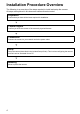
Installation Procedure Overview The following is an overview of the steps required to install and setup the camera. All steps are explained in this document unless otherwise noted. Preparation Confirm that you have all the items required for installation. Camera Diagram Confirm you know the names of the camera’s physical features. Connections Connect the camera to your network and to the power outlet. Setup Setup the camera (described in the included Setup Guide).
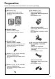
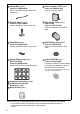
Preparation Confirm the following items are included in the camera’s packaging. Main Unit (1 pc.) AC Adaptor (1 pc.) The appearance of your camera depends on which model you have purchased. Order No. PQLV206Y Cord Length: About 3 m (9 feet 10 inches) BL-C140A/BL-C160A BL-C140 BL-C160 Screw A (6 pcs.) Order No. XTB4 + 20AFJ Used for wall mounting the camera. Order No. PQLV216CE1Z Cord Length: About 3 m (9 feet 10 inches) BL-C140CE/BL-C140E/BL-C160CE/ BL-C160E Screw B (3 pcs.) Order No.
Safety Wire (1 pc.) Power Transfer Unit (1 pc.) Order No. PQME10080Z Used to secure the camera when wall mounting it. Order No. PNWP3C160A Used to power the camera Flexible Stand (1 pc.) Right-Angle Joint (1 pc.) Order No. PQKL10082Z1 Used to attach the camera to the wall (with O-ring) Order No. PNYCC160A Used to protect the camera from water Foam Strip (1pc.) Self Bonding Tape (1pc.) Order No. PQHG10748Z Used to protect the camera from water Order No.
Camera Diagrams BL-C140 Front View A B C D A B C D Housing Indicator*1 Lens Lens cover E F G H I Safety wire hole DATA/POWER IN Stand mounting hole FACTORY DEFAULT RESET button Serial number and MAC address label Rear View G E H I F *1 See 1.1 Understanding the Camera Indicator in the Troubleshooting Guide on the CD-ROM for indicator meaning.
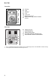
BL-C160 Front View A B C A B C D E F G Housing Light Indicator*1 Lens Lens cover Brightness sensor*2 Built-in sensor (pyroelectric infrared sensor) H I J K L Safety wire hole DATA/POWER IN Stand mounting hole FACTORY DEFAULT RESET button Serial number and MAC address label D E F G Rear View J H K L I *1 *2 8 See 1.1 Understanding the Camera Indicator in the Troubleshooting Guide on the CD-ROM for indicator meaning. The brightness sensor determines when the light turns on.
Choosing an Installation Location Please read the following information about the camera’s motion detection feature and built-in sensor (BL-C160 only) before deciding where to mount the camera. Detection Features Motion Detection Feature The camera detects changes in the images being displayed. Active Motion Detection Range • When the color of moving objects and the background are similar, motion may not be correctly detected.
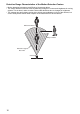
Detection Range Characteristics of the Motion Detection Feature • Motion detection becomes more difficult as it becomes darker. • The motion detection function works by detecting changes in contour and brightness in moving objects. This is done in order to reduce inaccurate detections due to changes in brightness. • The camera can easily detect motion when objects move sideways in front of the camera, but cannot easily detect motion when objects move toward the front of the camera.
Built-in Sensor (BL-C160 Only) The camera’s built-in sensor is a pyroelectric infrared sensor, which means it uses infrared rays to detect temperature differences within its range that are emitted naturally by people, animals, etc. The sensor can be used to trigger the camera to buffer (i.e., temporarily store) camera images in its memory. You can view these images later as desired. The sensor can also be used to trigger the camera to transfer images to someone or somewhere, by FTP, E-mail, or HTTP.
Detection Range Characteristics of the Built-in Sensor • The built-in sensor can easily detect temperature changes when objects move sideways in front of the camera, but cannot easily detect temperature changes when objects move toward the front of the camera.
Mounting Location • Mount the camera in a sheltered place where it is not directly exposed to direct sunlight or the elements. • To ensure that camera images are displayed properly, do not mount the camera on a ceiling. • Do not mount the camera upside down. If the Panasonic logo is upside down, the camera is upside down. • Mount the camera where objects pass the camera from the sides.
Recommended Installation Locations Top View Where it is easy to detect people coming off the street towards the property and where passing cars do not cause interference. It is easier to detect people when they pass in front of the camera. A sensor range cap can be attached to the camera to control the detection range. For more information, see page 27.
Installation Examples Example 1: For detecting people on your property Recommend Where it is easy to detect people coming off the street towards the property and where passing cars do not cause interference. It is easier to detect people when they pass in front of the camera. Not Recommend People or cars passing by on the street are easy to detect, but people approaching the camera by walking toward the front of the camera are difficult to detect.
Light Brightness (BL-C160 Only) The camera features a built-in light that can turn on automatically when it is dark, or when the camera’s motion detection or sensor features are triggered. The following brightness levels are measured 3 m (9 feet 10 inches) from the camera. Directly in front of the camera: about 8.5 lx 20° to the sides of the camera: about 2.5 lx Note that the light may not provide enough light to illuminate the surrounding area.
Connections Connect the camera to your router and to the power outlet as described below. • Before proceeding, confirm that your PC is connected to your router and can access the Internet. Also confirm that your router’s UPnP™ feature is enabled. (Most routers have UPnP™ turned off by default.
Camera Mounting Caution • Do not drive the screws into a soft material. Drive the screws into a secure area of the wall, such as a column, otherwise the camera may fall and be damaged. • Make sure you attach the safety wire when mounting the camera, to prevent the camera from falling. • Do not place the camera near any heat emitting devices (e.g., water heaters, air conditioners). (Placing the camera near heat emitting devices can cause the built-in sensor to not detect properly.
3 Mount the flexible stand firmly to the wall using screw A (included). • Do not drive the screws into a soft material. Drive the screws into a secure area of the wall, such as a column, otherwise the camera may fall and be damaged. • Use screws that are suited for the type of material the camera is mounted to. • Be careful not to nip the cable. • Make sure the flexible stand is firmly mounted on a beam (at least 25 mm [1 inch] thick) etc.
5 Wrap the included foam strip around the cable, insert it into the opening of the right-angle joint, and then wrap at least the first 50 mm (1 15/16 inches) of the cable using the included self bonding tape. • • • • Leave about 10 mm (3/8 inches) of the foam exposed, as shown. Stretch the tape to twice its length when you wrap the cable. Overlap the tape when you wrap the cable. Make sure that there are no gaps in the wrapped tape for water to enter.
8 Secure the safety wire to the wall using screw A (included) and washer L (included). • When mounting to a hard surface like mortar or concrete, use an anchor to help secure the camera to the wall. • Leave some slack in the safety wire, as shown. Safety wire Washer L Screw A 9 Connect a LAN cable to the power transfer unit and to the switching hub, router, etc. • The power transfer unit can be fixed in place with 2 pieces from screw A (4 mm x 20 mm [3/16 inch x 13/16 inch]).
When mounting on a mortar or concrete surface • Prepare anchors for 4 mm (3/16 inch) diameter screws for mounting. A Place the flexible stand on the wall where you plan to mount the flexible stand and mark the points where you are going to make holes. B Make holes with an electric drill. Insert anchors (customer-provided) into the holes and push them inside the holes with a hammer. • Mortar walls break easily when drilling. Be careful of pieces of mortar which may become loose and fall.
Adjusting Range and Sensitivity Preventing Sensor Interference (BL-C160 Only) If objects are interfering with the built-in sensor, use one of the included sensor range caps to cover the corresponding area of the sensor. For Built-in Sensors Example 1 If there are interfering objects (such as cars) on one side or corner of the screen, attach cap 1 or 2 to cover the desired area of the sensor.
Example 2 If there are interfering objects (such as heat emitting devices) being displayed on both sides of the screen, use cap 3 to block the parts of the sensor that are detecting the interfering objects (in this case on the left and right-hand sides).
Adjusting Motion Detection Sensitivity The sensitivity of the motion detection can be adjusted to match the installation environment. For more information, see 2.10 Adjusting Motion Detection Sensitivity in the Operating Instructions on the CD-ROM.
Adjusting Sensor Sensitivity (BL-C160 Only) By adjusting the sensitivity of the built-in sensor, the detection range can change in the following ways. The temperature and other qualities of the camera location may affect the detection range. For more information, see 2.9 Adjusting Sensor Sensitivity (BL-C160) in the Operating Instructions on the CD-ROM.
Sensor Range Caps (BL-C160 Only) When there are objects that you do not want to detect with the built-in sensor, a sensor range cap can be attached to the camera to control the detection range. There are 4 sensor range caps: the standard cap (attached at the time of purchase), cap 1, cap 2, and cap 3. Each cap blocks detection to various directions and degrees. Caps can be attached at 45° angles. Select the cap and attachment angle to best suit your needs.
Detection Ranges for the Sensor Range Caps Sensor range caps can be used to prevent detections when the temperature changes in certain areas of the detection range. Differing temperatures will affect how far the sensor can detect within the detection range. Confirm the different detection ranges in the following explanations. Please note that the below figures are a guide to the detection ranges when the Sensor Sensitivity is set to “Middle” (see page 26).
Temperature: 0 °C (32 °F) Temperature: 30 °C (86 °F) Top View Top View Detection range Detection range About 4 m (13 feet 1 inch) About 6 m (19 feet 8 inches) Top View Top View Detection range Detection range About 4 m (13 feet 1 inch) About 6 m (19 feet 8 inches) Top View Top View Detection range Detection range About 6 m (19 feet 8 inches) About 4 m (13 feet 1 inch) 29
Note 30
Note 31
© Panasonic System Networks Co., Ltd.