Operating Instructions Network Camera Model No. BL-VT164 Series BL-VP100 Series BL-VT164W BL-VP104W This manual covers the models: BL-VT164 Series (BL-VT164W, BL-VT164, BL-VT164WE, BL-VT164E, BL-VT164WU, BL-VT164U) and BL-VP100 Series (BL-VP104W, BL-VP104, BL-VP101, BL-VP104WE, BL-VP104E, BL-VP101E, BL-VP104WU, BL-VP104U, BL-VP101U). Before attempting to connect or operate this product, please read these instructions carefully and save this manual for future use.
Preface Preface About the user manuals There are 2 sets of operating instructions for the BL-VT164W, BL-VT164, BL-VP104W, BL-VP104, BL-VP101 (P model), BL-VT164WE, BL-VT164E, BL-VP104WE, BL-VP104E, BL-VP101E (E model), BL-VT164WU, BL-VT164U, BL-VP104WU, BL-VP104U, BL-VP101U (U model) as follows. • Installation Guide: Explains how to install and connect devices.
Preface Universal Plug and Play is described as UPnP™ or UPnP. Viewer software It is necessary to install the viewer software “Network Camera View 4S” to display images on a PC. This software can be installed directly from the camera or by selecting the [Install] button next to [Viewer Software] on the menu of the CD-ROM provided, and then following the on-screen instructions. IMPORTANT • • • • The default setting of “Automatic installation of viewer software” is “On”.
Table of Contents Table of Contents 1 Monitor images on a PC ..........................................................................7 1.1 1.2 1.3 1.4 Monitor images from a single camera .............................................................................7 About the “Live” page (BL-VT164W/BL-VT164) ...........................................................10 About the “Live” page (BL-VP104W/BL-VP104/BL-VP101) .........................................15 Monitor images from multiple cameras ....
Table of Contents 9.5.6 9.6 Configure the settings relating to the privacy zone (“Privacy zone” setup menu) (BL-VP104W/BL-VP104/BL-VP101) ..............................................................................70 Configure the settings relating to audio [Audio] (BL-VT164W/BL-VT164) ................72 10 Configure the multi-screen settings [Multi-screen] ............................75 11 Configure the alarm settings [Alarm] ...................................................77 11.1 11.2 11.3 11.
Table of Contents 15.7 15.7.1 15.7.2 Configure the schedule settings of the FTP periodic image transmission [FTP img. trans.] .............................................................................................................................137 How to set the schedules .............................................................................................137 How to delete the set schedule ....................................................................................
1 Monitor images on a PC 1 Monitor images on a PC The following are descriptions of how to monitor images from the camera on a PC. 1.1 Monitor images from a single camera 1. Start up the web browser. 2. Enter the IP address designated using the Panasonic “IP Setting Software” in the address box of the browser. • Example when entering an IPv4 address: http://URL registered using IPv4 address http://192.168.0.
1 Monitor images on a PC 3. Press the [Enter] key on the keyboard. → The window with the user name and password entry fields will be displayed. 4. Enter the user name and the password. The default user name and password are as follows.
1 Monitor images on a PC 5. Click the [OK] button. → The “Live” page will be displayed. Refer to VP101 VT164W VT164 : page 10, : page 15 for further information about the “Live” page. VP104W VP104 When “Off” is selected for “User auth.”, the authentication window will not be displayed before displaying live images. However, when the [Setup] button is clicked, an authentication window is displayed. A user name and password must be entered. The default user name and password are as follows.
1 Monitor images on a PC 1.2 About the “Live” page (BL-VT164W/BL-VT164) O P Q R S T A B C D E F U G H I M N J K L [select language] pull-down menu The camera’s display language can be selected. The default language can be set in the [Language] in the [Basic] settings. (®page 39) [Setup] button*1 Displays the setup menu. The button will turn green and the setup menu will be displayed. [Live] button Display the “Live” page. The button will turn green and the “Live” page will be displayed.
1 Monitor images on a PC [VGA] The letters “VGA” will turn green and images in the main area will be displayed in VGA size. [QVGA] The letters “QVGA” will turn green and images in the main area will be displayed in QVGA size. [640x360] The letters “640x360” will turn green and images in the main area will be displayed in 640 x 360 (pixels). [320x180] The letters “320x180” will turn green and images in the main area will be displayed in 320 x 180 (pixels).
1 Monitor images on a PC • Preset map-shot: Eight thumbnail images of the preset position 1-8 (®page 65) will be displayed orderly on a newly displayed window. When a thumbnail image is clicked, the camera moves to the respective position and live images will be displayed on the “Live” page. Note • Do not operate the browser until all the thumbnail images are displayed and the camera returns to the original position (where the camera was when “360 map-shot” or “Preset map-shot” was carried out).
1 Monitor images on a PC Snap shot button Click this button to take a picture (a still picture). The picture will be displayed on a newly opened window. When right-clicking on the displayed image, the pop-up menu will be displayed. It is possible to save the image on the PC by selecting “Save” from the displayed pop-up menu. When “Print” is selected, printer output is enabled. Note • The following setting may be necessary when using Windows 7 or Windows Vista.
1 Monitor images on a PC Note • • • *1 *2 *3 14 When operated by a lower access level user, images displayed on the screen may be changed temporarily. This does not affect operation of the camera. When the mouse is dragged to move the camera beyond its operable range, the camera will move to the requested direction and will stop at the end of the operable range. Then, the zoom ratio of the displayed image will automatically be adjusted.
1 Monitor images on a PC 1.3 About the “Live” page (BL-VP104W/BL-VP104/ BL-VP101) K L M N A B C D E F O G H I J [select language] pull-down menu The camera’s display language can be selected. The default language can be set in the [Language] in the [Basic] settings. (®page 39) [Setup] button*1 Displays the setup menu. The button will turn green and the setup menu will be displayed. [Live] button Display the “Live” page. The button will turn green and the “Live” page will be displayed.
1 Monitor images on a PC [QVGA] The letters “QVGA” will turn green and images in the main area will be displayed in QVGA size. [640x360] The letters “640x360” will turn green and images in the main area will be displayed in 640 x 360 (pixels). [320x180] The letters “320x180” will turn green and images in the main area will be displayed in 320 x 180 (pixels). [800x600] VP104W VP104 The letters “800x600” will turn green and images in the main area will be displayed in 800 x 600 (pixels).
1 Monitor images on a PC Note • The following setting may be necessary when using Windows 7 or Windows Vista. Click “Internet Options” on the Tools menu of Internet Explorer, and then click the [Security] tab. Select “Trusted Sites”, and click “Sites”. Register the camera address on the “Website” in the “Trusted Sites” window. Main area*2 Images from the camera will be displayed in this area.
1 Monitor images on a PC 1.4 Monitor images from multiple cameras Images from multiple cameras can be displayed on a multi-screen. Images from 4 cameras (up to 16 cameras) can be displayed simultaneously. To display images on a multi-screen, it is necessary to register cameras in advance. 4 cameras can be registered as a group and up to 4 groups (16 cameras) can be registered.
2 Monitor images on a cellular phone/mobile terminal 2 Monitor images on a cellular phone/mobile terminal 2.1 Monitor images on a cellular phone It is possible to connect to the camera using a cellular phone via the Internet and monitor images (JPEG only) from the camera on the screen of the cellular phone. It is also possible to refresh images to display the latest image or perform panning, tilting and zooming operations.
2 Monitor images on a cellular phone/mobile terminal 1. Access to “http://IP address/mobile”*1 or “http://Host name registered in the DDNS server/mobile” using a cellular phone. → Images from the camera will be displayed.
2 Monitor images on a cellular phone/mobile terminal J Functions A Pan/tilt*2 VT164W VT164 B Zooming control*2 VT164W VT164 Outline of functions Controls the camera direction. The camera will pan or tilt to each direction by pressing the corresponding dial key. It is possible to perform zooming operations of the camera by pressing “*” or “#”. C Refresh Refreshes the camera images by pressing the dial key “5”. D Resolution control Changes the image capture size by pressing the dial key “0”.
2 Monitor images on a cellular phone/mobile terminal Note • • • • • • *1 *2 When the HTTP port number is changed from “80”, enter “http://IP address: (colon) + port number/ mobile”*1 in the address box of the browser. When using the DDNS function, access to “http://Host name registered in the DDNS server: (colon) + port number/mobile”. When “HTTPS” is selected for “HTTPS” - “Connection” on the [Network] tab of the “Network” page, enter as follows.
2 Monitor images on a cellular phone/mobile terminal 1. Access to “http://IP address/cam”*1 or “http://Host name registered in the DDNS server/cam”*2 using a mobile terminal. → Images from the camera will be displayed. A B C D Live images area Displays images from the camera. Operation buttons area When functions are selected in the function selection area D, buttons to operate those functions are displayed. Zoom operation area Buttons to operate the zoom are displayed.
2 Monitor images on a cellular phone/mobile terminal 2. Click the button of the function that you want to operate. F A B C VT164 Pan/Tilt VT164W VT164 Preset VT164W Resolution control VT164 AUX control VT164W Privacy Mode control VT164W VT164 Zoom display VT164W Each function is explained below.
2 Monitor images on a cellular phone/mobile terminal VT164 Pan/Tilt VT164W Press the button to display the buttons used to operate pan/tilt on the screen. The pan/tilt can be adjusted in each direction with the , , , and buttons. VT164 Preset VT164W Press the button to display the buttons used to select the preset position on the screen. Camera images are displayed of the registered preset camera directions according to the preset numbers selected from the buttons.
2 Monitor images on a cellular phone/mobile terminal Resolution control Press the button to display the buttons used to select the resolution on the screen. The resolution can be changed by selecting a resolution setting from the buttons. • Image in the aspect ratio of “4:3” VT164W VT164 VP104W VP104 : Changes the image capture size between 320x240, 640x480 (default), and 800x600. VP101 : Changes the image capture size between 320x240 and 640x480 (default).
2 Monitor images on a cellular phone/mobile terminal VT164 AUX control VT164W Press the button to display the buttons used to operate the AUX output on the screen. The AUX output terminals can be controlled with the and buttons. This function is only displayed when [Terminal 3] is set to [AUX output] on the settings menu.
2 Monitor images on a cellular phone/mobile terminal VT164 Privacy Mode control VT164W Press the button to display the buttons used to operate the privacy mode on the screen. The privacy mode can be enabled and disabled with the To activate privacy mode, press To deactivate privacy mode, press 28 Operating Instructions . . and buttons.
2 Monitor images on a cellular phone/mobile terminal VT164 Zoom display VT164W The camera’s zoom can be operated with the , , and buttons. Note • • • • • • • • *1 *2 You can change the image size displayed on the mobile terminal by accessing the following addresses.
3 Action at an alarm occurrence 3 Action at an alarm occurrence The alarm action (camera action at an alarm occurrence) will be performed when the following alarms occur. 3.1 Alarm type • • • • VT164 : When connecting an alarm device such as a sensor to the EXT I/O Terminal alarm VT164W connectors 1-3 of the camera, the alarm action will be performed when the connected alarm device is activated.
3 Action at an alarm occurrence Notify of alarm occurrences to the designated IP addresses (Panasonic alarm protocol notification) This function is available only when a Panasonic device, such as the network disk recorder, is connected to the system. When “On” is selected for “Panasonic alarm protocol”, the connected Panasonic device will be notified that the camera is in the alarm state.
4 Transmit images onto an FTP server 4 Transmit images onto an FTP server Images can be transmitted to an FTP server. By configuring the following settings, transmission of images captured at an alarm occurrence or captured at a designated interval to an FTP server will become available. IMPORTANT • When using this function, set the user name and the password to access the FTP server to restrict users who can log into the FTP server. 4.
5 About the network security 5 About the network security 5.1 Equipped security functions The following security functions are featured in this camera. Access restrictions by the host authentication and the user authentication It is possible to restrict users from accessing the camera by setting the host authentication and/or the user authentication to “On”. (®page 94, page 95) Access restrictions by changing the HTTP port It is possible to prevent illegal access such as port scanning, etc.
6 Display the setup menu from a PC 6 Display the setup menu from a PC The settings of the camera can be configured on the setup menu. IMPORTANT • The setup menu is only operable by users whose access level is “1. Administrator”. Refer to page 94 for how to configure the access level. 6.1 How to display the setup menu 1. Display the “Live” page. (®page 7) 2. Click the [Setup] button on the “Live” page. When the authentication window is displayed, enter the user name and password, then click [OK].
6 Display the setup menu from a PC 6.2 How to operate the setup menu B A Menu buttons Setup page 1. Click the desired button in the frame on the left of the window to display the respective setup menu. When there are tabs at the top of the “Setup” page displayed in the frame on the right of the window, click the desired tab to display and configure the setting items relating to the name of the tab. 2. Complete each setting item displayed in the frame on the right of the window. 3.
6 Display the setup menu from a PC The edited settings in field A will not be applied unless the [Set] button (B) below field (A) is clicked. In the same manner as above, click the [Set] button (D) below field C when completing the setting items in field C.
6 Display the setup menu from a PC 6.3 About the setup menu window O A B C D E F P G H I J K L M N [Setup] button Display the “Setup” page. [Live] button Display the “Live” page. [Basic] button Displays the “Basic” page. The basic settings such as time and date and camera title can be configured on the “Basic” page. (®page 39) [Internet] button Displays the “Internet” page. The Internet settings such as UPnP (Auto port forwarding), DDNS (Viewnetcam.
6 Display the setup menu from a PC [Advanced func.] button Displays the “Advanced func.” page. The setting relating to the XML notification, destinations of information about the face detection and the settings relating to the face detection can be configured on the “Advanced func.” page. (®page 91) [User mng.] button Displays the “User mng.” page. The settings relating to the authentication such as users and PCs restrictions for accessing the camera can be configured on the “User mng.” page.
7 Configure the basic settings of the camera [Basic] 7 Configure the basic settings of the camera [Basic] The basic settings such as camera title, time and date, etc. can be configured on the “Basic” page. (®page 34, page 35) [Camera title] Enter the title of the camera. Click the [Set] button after entering the title of the camera. The entered title will be displayed in the “Camera title” field.
7 Configure the basic settings of the camera [Basic] IMPORTANT • • Depending on the conditions such as the ambient temperature and operating period, the configured time & date may not be accurate. Use an NTP server when the more accurate time & date setting is required for the system operation. (®page 101) [Time display format] Select the time display format from “24h”, “12h” and “Off”. Enter the current hour reflecting this setting when entering the current time and date for “Date/time”.
7 Configure the basic settings of the camera [Basic] • • Available characters: 0-9, A-Z and the following marks. !"#$%&'()*+,-./:;=? Default: None (blank) [OSD] - [Position] Select the position where the time and date and a character string to be displayed on the image of the “Live” page. • Upper left: The above information will be displayed at the upper left corner of the main area on the “Live” page.
7 Configure the basic settings of the camera [Basic] Operation status Indicator status During the initialization Blinks orange ® Lights off Port forwarding error caused by the UPnP function Blinks orange (in 2 seconds intervals (on for 1 second / off for 1 second)) Trouble happening on the camera Blinks red When there is a body heat sensor detection Lights orange (for 1 second) VT164W VT164 During privacy mode • Lights red WIRELESS indicator (Red/Orange/Green) VT164W blink as follows dependi
7 Configure the basic settings of the camera [Basic] IMPORTANT • • It is impossible to display images and to receive/transmit audio between the camera and the PC when the viewer software “Network Camera View 4S” is not installed on the PC. The number of the viewer software installations can be checked on the [Upgrade] tab of the “Maintenance” page. [Language] Select the language to initially display when the camera is accessed from the following.
8 Configure the Internet settings [Internet] 8 Configure the Internet settings [Internet] The settings for connecting the camera to the Internet can be configured on the “Internet” page. (®page 34, page 35) The settings relating to UPnP (Auto port forwarding), DDNS (Viewnetcam.com), and network settings for the Internet can be configured on this page. [UPnP (Auto port forwarding)] Select “On” or “Off” to determine whether or not to use the port forwarding function of the router.
8 Configure the Internet settings [Internet] [Recommended network setting for internet] The recommended settings for connecting to the Internet are performed here. By clicking the [Set] button, a dialog displaying how the following settings will change is displayed. Click the [OK] button after checking the settings to change the settings to the displayed values. – [JPEG/H.264] tab on the “Image/Audio” page [H.264(1)]/[H.
9 Configure the settings relating to images and audio [Image/Audio] (BL-VT164W/BL-VT164)/ Configure the settings relating to images [Image] (BL-VP104W/BL-VP104/BL-VP101) 9 Configure the settings relating to images and audio [Image/Audio] (BL-VT164W/BL-VT164)/ Configure the settings relating to images [Image] (BL-VP104W/BL-VP104/BL-VP101) VT164W VT164 : The settings relating to JPEG and H.264 images such as the settings of image quality, audio, etc. can be configured on this page.
9 Configure the settings relating to images and audio [Image/Audio] (BL-VT164W/BL-VT164)/ Configure the settings relating to images [Image] (BL-VP104W/BL-VP104/BL-VP101) 9.2 Configure the settings relating to JPEG images [JPEG/H.264] Click the [JPEG/H.264] tab on the “Image/Audio” page. (®page 34, page 35) JPEG Configure the settings such as “Refresh interval (JPEG)*”, “Image capture size” and “Image quality” on this section. Refer to page 49 for further information about the settings relating to H.
9 Configure the settings relating to images and audio [Image/Audio] (BL-VT164W/BL-VT164)/ Configure the settings relating to images [Image] (BL-VP104W/BL-VP104/BL-VP101) VP101 : 320x180/ 640x360 • Default: 640x360 VT164W VT164 VP104W VP104 /VGA VP101 [Image quality] Select the image quality of JPEG images displayed initially on the “Live” page. • Default: Quality1 [Image quality setting] Select two types of image quality of JPEG images for each image capture size.
9 Configure the settings relating to images and audio [Image/Audio] (BL-VT164W/BL-VT164)/ Configure the settings relating to images [Image] (BL-VP104W/BL-VP104/BL-VP101) 9.3 Configure the settings relating to H.264 images [JPEG/H.264] Click the [JPEG/H.264] tab on the “Image/Audio” page.
9 Configure the settings relating to images and audio [Image/Audio] (BL-VT164W/BL-VT164)/ Configure the settings relating to images [Image] (BL-VP104W/BL-VP104/BL-VP101) Configure the settings relating to H.264 image such as “Max bit rate (per client)”, “Image capture size”, “Image quality”, etc. in this section. Refer to page 47 for the settings relating to JPEG images.
9 Configure the settings relating to images and audio [Image/Audio] (BL-VT164W/BL-VT164)/ Configure the settings relating to images [Image] (BL-VP104W/BL-VP104/BL-VP101) H.264(1)/H.264(2) [H.264 transmission] Select “On” or “Off” to determine whether or not to transmit H.264 images. • On: Transmits H.264 images. • Off: Does not transmit H.264 images. • Default: On Note • • • When “On” is selected for “H.264 transmission” in “H.264(1)” or “H.264(2)”, displaying of H.
9 Configure the settings relating to images and audio [Image/Audio] (BL-VT164W/BL-VT164)/ Configure the settings relating to images [Image] (BL-VP104W/BL-VP104/BL-VP101) [Transmission priority] Select a transmission priority for H.264 images from the following. • Constant bit rate: H.264 images will be transmitted with the bit rate selected for “Max bit rate (per client)*”. • Frame rate: H.264 images will be transmitted with the frame rate selected for “Frame rate*”.
9 Configure the settings relating to images and audio [Image/Audio] (BL-VT164W/BL-VT164)/ Configure the settings relating to images [Image] (BL-VP104W/BL-VP104/BL-VP101) [Refresh interval] Select an interval (I-frame interval; 0.2 - 5 seconds) to refresh the displayed H.264 images. If using under a network environment with frequent error occurrences, shorten the refresh interval for H.264 to diminish image distortions. However, the refresh interval may be longer than the set value. 0.2s/ 0.25s/ 0.33s/ 0.
9 Configure the settings relating to images and audio [Image/Audio] (BL-VT164W/BL-VT164)/ Configure the settings relating to images [Image] (BL-VP104W/BL-VP104/BL-VP101) Note • When audio is transmitted from the unit, the port number to be used will be the multicast port number plus “1000”. [Multicast TTL/HOPLimit]*3 Enter a value for “Multicast TTL/HOPLimit”. • Available value: 1-254 • Default: 16 IMPORTANT • • When transmitting an H.
9 Configure the settings relating to images and audio [Image/Audio] (BL-VT164W/BL-VT164)/ Configure the settings relating to images [Image] (BL-VP104W/BL-VP104/BL-VP101) 9.4 Configure the settings relating to the camera operations [Cam. Function] (BL-VT164W/BL-VT164) Click the [Cam. Function] tab on the “Image/Audio” page. (®page 34, page 35) Configure the settings relating to camera operations. [Home position] A preset position (®page 65) can be set as the home position.
9 Configure the settings relating to images and audio [Image/Audio] (BL-VT164W/BL-VT164)/ Configure the settings relating to images [Image] (BL-VP104W/BL-VP104/BL-VP101) • • • On: A still image will be held on the screen until the camera has moved to the preset position. Off: Images from the camera will be displayed even when the camera is moving to the preset position. Default: Off [Extra zoom] Select the extra zoom setting from the following. • On (Max X1.
9 Configure the settings relating to images and audio [Image/Audio] (BL-VT164W/BL-VT164)/ Configure the settings relating to images [Image] (BL-VP104W/BL-VP104/BL-VP101) 9.5 Configure the settings relating to images and the preset positions [Image/Position] (BL-VT164W/ BL-VT164)/ Configure the settings relating to image adjust, extra zoom, and privacy zone [Image/Privacy] (BL-VP104W/BL-VP104/BL-VP101) VT164W VT164 : Click the [Image/Position] tab on the “Image/Audio” page.
9 Configure the settings relating to images and audio [Image/Audio] (BL-VT164W/BL-VT164)/ Configure the settings relating to images [Image] (BL-VP104W/BL-VP104/BL-VP101) [Privacy zone] Click the [Setup>>] button to display the setup menu that can configure the settings relating to the privacy zone. The setup menu will be displayed in a newly opened window. (®page 68, page 70) 9.5.
9 Configure the settings relating to images and audio [Image/Audio] (BL-VT164W/BL-VT164)/ Configure the settings relating to images [Image] (BL-VP104W/BL-VP104/BL-VP101) [Adaptive black stretch] Select “On” or “Off” to determine whether or not to activate the darkness compensation function. The darkness compensation function can make darker parts of images brighter by digital image processing. • • • On: Activates the darkness compensation function. Off: Deactivates the darkness compensation function.
9 Configure the settings relating to images and audio [Image/Audio] (BL-VT164W/BL-VT164)/ Configure the settings relating to images [Image] (BL-VP104W/BL-VP104/BL-VP101) [Back light compensation (BLC)] Select “On” or “Off” to determine whether or not to activate the back light compensation (BLC) function. The back light compensation function can compensate back light by setting mask areas on brighter parts of images. • • • On: Mask areas will be set automatically.
9 Configure the settings relating to images and audio [Image/Audio] (BL-VT164W/BL-VT164)/ Configure the settings relating to images [Image] (BL-VP104W/BL-VP104/BL-VP101) • • Off: Images will be captured with the fixed gain level. Default: On(High) [Auto slow shutter] The electronic sensitivity enhancement (sensitivity up) can be carried out by adjusting the storage time of the sensor. The following are available for the recording duration. VT164W VT164 VP104W VP104 : Off(1/30s), Max.2/30s, Max.
9 Configure the settings relating to images and audio [Image/Audio] (BL-VT164W/BL-VT164)/ Configure the settings relating to images [Image] (BL-VP104W/BL-VP104/BL-VP101) Click the [Reset] button to reset the color to the default. • Default: 128 [Blue gain] Adjust the blue color of images. When the cursor is moved in the “+” direction, the blue color will become thicker. When the cursor is moved in the “–” direction, the blue color will be thinner.
9 Configure the settings relating to images and audio [Image/Audio] (BL-VT164W/BL-VT164)/ Configure the settings relating to images [Image] (BL-VP104W/BL-VP104/BL-VP101) 1. Display the “Image adjust” setup menu. (®page 57) 2. Click the [Start] button of “Mask area”. VT164 : Borders will appear and the image displayed on the [Image/Position] tab will be → VT164W divided into 48 (6x8). VP104W VP104 : Borders will appear and the image displayed on the [Image/Privacy] tab will be divided into 48 (6x8).
9 Configure the settings relating to images and audio [Image/Audio] (BL-VT164W/BL-VT164)/ Configure the settings relating to images [Image] (BL-VP104W/BL-VP104/BL-VP101) Note : “Mask area” can be set only when “4:3” is selected for “Aspect ratio”. If the “Aspect ratio” is changed to “16:9” after setting the mask area, the setting of the mask area is maintained. VP101 • 3. Click the divided areas to be masked. → The clicked areas will be masked and will become white.
9 Configure the settings relating to images and audio [Image/Audio] (BL-VT164W/BL-VT164)/ Configure the settings relating to images [Image] (BL-VP104W/BL-VP104/BL-VP101) A. Image in the aspect ratio of “16:9” B. Areas where the image is not displayed when A “4:3” is selected for the aspect ratio C. Image in the aspect ratio of “4:3” (Being cut out from the aspect ratio of “16:9”) C B : When “16:9” is selected for the aspect ratio of JPEG/H.
9 Configure the settings relating to images and audio [Image/Audio] (BL-VT164W/BL-VT164)/ Configure the settings relating to images [Image] (BL-VP104W/BL-VP104/BL-VP101) IMPORTANT • When the zoom factor is 1.5x or more, the setting of the preset positions will become unavailable. Note • Depending on the environment (such as when the temperature is below 5° C (41 °F), for example), the moving speed of the camera to the preset position may become slower. 9.5.3.1 Register the preset positions 1.
9 Configure the settings relating to images and audio [Image/Audio] (BL-VT164W/BL-VT164)/ Configure the settings relating to images [Image] (BL-VP104W/BL-VP104/BL-VP101) 3. To display the preset ID on the “Live” page, select “On” for “Preset ID” and enter the desired position title to be displayed. 4. Click the [Set] button. 5. The settings for each item such as “Back light compensation (BLC)” can be configured for each position independently.
9 Configure the settings relating to images and audio [Image/Audio] (BL-VT164W/BL-VT164)/ Configure the settings relating to images [Image] (BL-VP104W/BL-VP104/BL-VP101) [Set] button Registers the preset positions. [Delete] button Deletes the preset position specified by the position number. [Close] button Click this button to close the “Preset position” setup menu. 9.5.
9 Configure the settings relating to images and audio [Image/Audio] (BL-VT164W/BL-VT164)/ Configure the settings relating to images [Image] (BL-VP104W/BL-VP104/BL-VP101) • Depending on the panning/tilting direction (especially when the tilting degree is 45° - 90°) and the zooming factor, the area set as the privacy zone may become visible. Make sure that each of the set privacy zone is not visible after setting it. Privacy zone [Display type] Select a display type of the privacy zone from the following.
9 Configure the settings relating to images and audio [Image/Audio] (BL-VT164W/BL-VT164)/ Configure the settings relating to images [Image] (BL-VP104W/BL-VP104/BL-VP101) Note • • • • Set the privacy zone larger than the size of an object to be hidden. Panning, tilting and zooming operations can also be carried out on the [Image/Position] tab.
9 Configure the settings relating to images and audio [Image/Audio] (BL-VT164W/BL-VT164)/ Configure the settings relating to images [Image] (BL-VP104W/BL-VP104/BL-VP101) • • • Gray: The privacy zones will be displayed in gray. Off: Does not display the privacy zones. Default: Off Note • Set the privacy zone larger than the size of an object to be hidden. [Close] button Click this button to close the “Privacy zone” setup menu.
9 Configure the settings relating to images and audio [Image/Audio] (BL-VT164W/BL-VT164)/ Configure the settings relating to images [Image] (BL-VP104W/BL-VP104/BL-VP101) 9.6 Configure the settings relating to audio [Audio] (BL-VT164W/BL-VT164) Click the [Audio] tab on the “Image/Audio” page. (®page 34, page 35) The settings relating to audio can be configured on this page. Note • • Images and audio will not be synchronized. Therefore, images and audio may not always match.
9 Configure the settings relating to images and audio [Image/Audio] (BL-VT164W/BL-VT164)/ Configure the settings relating to images [Image] (BL-VP104W/BL-VP104/BL-VP101) Note • G.711 is available only when “Mic input” is selected for “Audio transmission/reception”. [Audio bit rate] Select “16kbps” or “32kbps” for the audio bit rate used to transmit/receive audio data.
9 Configure the settings relating to images and audio [Image/Audio] (BL-VT164W/BL-VT164)/ Configure the settings relating to images [Image] (BL-VP104W/BL-VP104/BL-VP101) • • Audio may temporarily be interrupted and noise may be heard when multiple users are accessing the camera concurrently. It may be possible to diminish the interruption or noise by setting a longer interval for “Audio output interval (PC to Camera)”. Audio may sometimes not be heard depending on the network environment.
10 Configure the multi-screen settings [Multi-screen] 10 Configure the multi-screen settings [Multi-screen] The cameras from which images are to be displayed on a multi-screen can be registered on the “Multi-screen” page. (®page 34, page 35) [IP address] Enter the IP address or the host name of the camera to be used for the multi-screen. 4 cameras can be registered as a group and up to 4 groups (16 cameras) can be registered.
10 Configure the multi-screen settings [Multi-screen] – Example when entering an IPv4 address: http://192.168.0.10:8080 – Example when entering an IPv6 address: http://[2001:db8:0:0:0:0:0:1]:8080 To access the cameras using the HTTPS protocol, enter as follows: Example of entry: https://192.168.0.10/ • Available number of characters: 1 - 128 characters • Default: (Cam. 1) selfcamera, (Cam.
11 Configure the alarm settings [Alarm] 11 Configure the alarm settings [Alarm] The settings relating to alarm occurrences such as settings for the alarm action at an alarm occurrence, the VMD area settings, and the alarm occurrence notification can be configured on this page. The “Alarm” page has 3 tabs; the [Alarm] tab, the [VMD area] tab and the [Notification] tab. 11.1 Configure the settings relating to the alarm action [Alarm] Click the [Alarm] tab on the “Alarm” page.
11 Configure the alarm settings [Alarm] [Terminal 3] VT164W VT164 Determine how to use terminal 3. • Off: Not used. • Alarm input: Receives alarms. – Close: An alarm is detected when the terminal status is changed to “On”. – Open: An alarm is detected when the terminal status is changed to “Off”. • AUX output: AUX output will be supplied. The [AUX] buttons will be displayed on the “Live” page.
11 Configure the alarm settings [Alarm] [Originating port number] Select a port number to be used to receive the command alarm. • Available range: 1-65535 • Default: 8181 The following port numbers are unavailable since they are already in use. 20, 21, 23, 25, 42, 53, 67, 68, 69, 80, 110, 123, 161, 162, 443, 554, 995, 10669, 10670, 59000-61000 11.2 Configure the settings relating to the camera action on alarm occurrence [Alarm] (BL-VT164W/ BL-VT164) Click the [Alarm] tab on the “Alarm” page.
11 Configure the alarm settings [Alarm] [Body heat sensor] Select an action to be taken when a body heat sensor is detected from the following. • Off: Does not take any action even when a body heat sensor is detected. • 1-64: When the registered preset position is selected, the camera will move to the selected preset position when a body heat sensor is detected. • Default: Off [VMD alarm] Select an action to be taken when a VMD alarm is detected from the following.
11 Configure the alarm settings [Alarm] Alarm image [FTP >>] When “FTP >>” is clicked, the [FTP] tab of the “Server” page will be displayed. (®page 100) [Alarm image FTP transmission] Select “On” or “Off” to determine whether or not to transmit the alarm image to the FTP server. • Default: Off [Directory name] Enter the directory name where the alarm images are to be saved. For example, enter “/ALARM” to designate the directory “ALARM” under the root directory of the FTP server.
11 Configure the alarm settings [Alarm] [Image compression rate upon alarm detection] Select “On” or “Off” to determine whether or not to change the image quality of “Quality1” (®page 47) upon alarm detection. • On: Images will be transmitted with the image quality selected for “Image quality upon alarm detection”. • Off: Does not change the image quality upon alarm detection. • Default: Off [Image quality upon alarm detection] Image quality can be changed upon an alarm occurrence.
11 Configure the alarm settings [Alarm] • • Close: The alarm output terminal will close when outputting the alarm signals. (Normally open) Default: Close Note • When “Open” is selected, the alarm signal will be output for about 20 seconds when the power of the unit is turned on. [Pulse width] When “Pulse” is selected for “Alarm output”, select an alarm output terminal duration from the following. • Available range: 1-120s • Default: 1s 11.
11 Configure the alarm settings [Alarm] 11.6 Configure the VMD settings [VMD area] Click the [VMD area] tab on the “Alarm” page. (®page 34, page 35) The video motion detection areas can be set on this page. VT164W VT164 : The VMD areas can be set up to 4 areas for each preset position (maximum 64 preset positions). When motion is detected in the set area, it will be regarded as an alarm. The camera can be configured to take an alarm action even when the camera is not at the preset position.
11 Configure the alarm settings [Alarm] VMD information addition [Information addition] Select “On” or “Off” to determine whether or not to add VMD information to superimposed image data. The VMD information can be searched by some Panasonic network disk recorders. Refer to the operating instructions of the connected devices for further information about the functions and settings. • Default: Off Procedure for setting the VMD area Set the areas to activate the VMD function.
11 Configure the alarm settings [Alarm] [Status] Select “On” or “Off” to determine whether or not to activate each VMD area. • On: Activates the respective VMD area. • Off: Inactivates the respective VMD area. • Default: Off [Detection area] Adjust the size of the VMD area using the slider. The smaller the selected value is, the higher the sensitivity of VMD area becomes. The current value (1-10) will be displayed on the right of the slider.
11 Configure the alarm settings [Alarm] 3. Click the [Set] button after completing the settings. IMPORTANT • The setting will not be applied unless the [Set] button is clicked. 4. To invalidate the VMD area, click the [Set] button after selecting “Off” for “Status” of the VMD area to be invalidated. → The outline of the invalidated VMD area will turn to a dotted line. When the VMD area is invalidated, no alarm will occur even when a motion can be recognized in the area. 5.
11 Configure the alarm settings [Alarm] [E-mail notification] Select “On” or “Off” to determine whether or not to provide notification by E-mail according to the settings for the “Alarm” and “Diag.” checkboxes of “Destination of notification” below. – When an alarm is detected (“Alarm”) • Default: Off [Alarm image attachment] Select “On” or “Off” to determine whether or not to attach an image to the E-mail to be sent when an alarm is detected.
11 Configure the alarm settings [Alarm] The settings relating to Panasonic alarm protocol can be configured in this section. Panasonic alarm protocol notification [Panasonic alarm protocol] Select “On” or “Off” to determine whether or not to provide notification by Panasonic alarm protocol according to the settings for the “Alarm” and “Diag.” checkboxes of “Destination of notification” below.
11 Configure the alarm settings [Alarm] • • Available range: 0-30 Default: 2 Destination of notification [Address 1] - [Address 8] Enter the destination IP address or host name of the Panasonic alarm protocol from the following. Up to 8 destination server addresses can be registered. • [Alarm] checkbox: When the checkbox is selected, the Panasonic alarm notification will be provided upon an alarm occurrence. • [Destination Server address]: Enter the destination server address or host name.
12 Configure the setting relating to the image recognition [Advanced func.] 12 Configure the setting relating to the image recognition [Advanced func.] The settings relating to the XML notification and the settings relating to the face detection can be configured on the “Advanced func.” page. The “Advanced func.” page has 2 tabs; the [XML notification] tab and the [Face detection] tab. 12.
12 Configure the setting relating to the image recognition [Advanced func.] • Default: Off [Notification data] Select the type of data notification. Select one of the following. • Face data Detection info.(Original)/Detection info.(Advanced) Default: Detection info.(Original) [Notification interval] Select the notification interval. • Face data 1s/2s/3s/4s/5s/6s/10s/15s/20s/30s/1min Default: 1s Note • When [Notification data] is set to “Detection info.
12 Configure the setting relating to the image recognition [Advanced func.] 12.2 Configuration of the settings relating to the face detection [Face detection] Click the [Face detection] tab on the “Advanced func.” page. The settings relating to displaying the frame to be used for the face detection and the settings relating to the face detection information attached to the image can be configured. IMPORTANT • The face detection function shall not guarantee the detection of faces in an image.
13 Configure the settings relating to the authentication [User mng.] 13 Configure the settings relating to the authentication [User mng.] The settings relating to the authentication such as users and PCs restrictions for accessing the camera with a PC or cellular phone/mobile terminal can be configured on the “User mng.” page. The “User mng.” page has 3 tabs; the [User auth.] tab, the [Host auth.] tab and the [System] tab. 13.1 Configure the settings relating to the user authentication [User auth.
13 Configure the settings relating to the authentication [User mng.] Note • When the [Authentication] setting has been changed, close the web browser, and then access the camera again. [User name] Enter a user name. • Available number of characters: 1 - 32 characters • Unavailable characters: " & : ; \ • Default: None (blank) [Password] [Retype password] Enter a password.
13 Configure the settings relating to the authentication [User mng.] The restriction settings of PCs (IP address) from accessing the camera can be configured on this page. [Host auth.] Select “On” or “Off” to determine whether or not to authenticate the host. • Default: Off [IP address] Enter the IP address of the PC to be allowed to access the camera. Host name cannot be entered for the IP address. Note • • When “IP address/subnet mask” is entered, it is possible to restrict PCs in each subnet.
13 Configure the settings relating to the authentication [User mng.] The description below is the configuration of the priority stream that can transmit images without deteriorating the image quality and refresh interval even when multiple users access concurrently. Priority stream [Activation] Select “On” or “Off” to determine whether or not to use the priority stream.
13 Configure the settings relating to the authentication [User mng.] [Image capture size] Select the image capture size from the following. This setting is validated only when “JPEG” is selected for “Stream type”.
14 Configure the settings of the servers [Server] 14 Configure the settings of the servers [Server] The settings relating to the E-mail server, the FTP server and the NTP server can be configured on this page. The “Server” page has 3 tabs; the [E-mail] tab, the [FTP] tab and the [NTP] tab. 14.1 Configure the settings relating to the E-mail server [E-mail] Click the [E-mail] tab on the “Server” page.
14 Configure the settings of the servers [Server] IMPORTANT • When entering the host name for “SMTP server address” or “POP server address”, it is necessary to configure the DNS settings on the [Network] tab of the “Network” page. (®page 104) [Authentication] • Type Select the authentication method to send E-mails from the following. – None: It is not necessary to clear any authentication to send E-mails.
14 Configure the settings of the servers [Server] [FTP server address] Enter the IP address or the host name of the FTP server. • Available number of characters: 1 - 128 characters • Available characters: Alphanumeric characters, the colon (:), the period (.), the underscore (_), and the hyphen (-). IMPORTANT • When entering the host name for “FTP server address”, it is necessary to configure the DNS settings on the [Network] tab of the “Network” page.
14 Configure the settings of the servers [Server] IMPORTANT • Use an NTP server when the more accurate time & date setting is required for the system operation. [Time adjustment] Select the time adjustment method from the following. Time adjusted by the selected method will be used as the standard time of the camera. • Manual: Time set on the “Basic” page will be used as the standard time of the camera.
14 Configure the settings of the servers [Server] The following port numbers are unavailable since they are already in use. 20, 21, 23, 25, 42, 53, 67, 68, 69, 80, 110, 161, 162, 443, 995, 10669, 10670 [Time adjustment interval] Select an interval (1 - 24 hours: in 1 hour intervals) of synchronization with the NTP server. • Default: 1h [Time zone] Select a time zone corresponding to the location where the camera is in use.
15 Configuring the network settings [Network] 15 Configuring the network settings [Network] The network settings and the settings relating to DDNS (Dynamic DNS) and SNMP (Simple Network management Protocol) can be configured on the “Network” page. The “Network” page has 4 tabs; the [Network] tab, the [DDNS] tab, the [SNMP] tab and the [FTP img. trans.] tab. 15.1 Configure the network settings [Network] Click the [Network] tab on the “Network” page.
15 Configuring the network settings [Network] IPv4 network [Network Settings] Select the method of how to configure the IP address from the following. • Static: The IP address is configured by entering manually on “IP address(IPv4)”. • DHCP: The IP address is configured using the DHCP function. • Auto(AutoIP): The IP address is configured using the DHCP function. When the DHCP server is not found, the IP address is automatically configured.
15 Configuring the network settings [Network] • Default: Auto(Advanced) Note • When “Auto(AutoIP)” is selected and the IP address cannot be obtained from the DHCP server, an IP address not used in the same network will be searched within 169.254.1.0 - 169.254.254.255. [IP address(IPv4)] When not using the DHCP function, enter the IP address of the camera. Do not enter an IP address already in use (for the PCs and the other network cameras). • Default: 192.168.0.
15 Configuring the network settings [Network] Note • When connecting to the manually configured IPv6 address beyond the router, use an IPv6 compatible router and turn on the automatic IPv6 address assignment function. In this case, it is necessary to configure IPv6 address including prefix information provided from the IPv6 compatible router. Refer to the manuals provided with the router for further information. [DHCPv6] Select “On” or “Off” to determine whether or not to use the IPv6 DHCP function.
15 Configuring the network settings [Network] UPnP This camera support UPnP (Universal Plug and Play). By using the UPnP function, it becomes possible to configure the following automatically. • Configuration of the port forwarding function of the router (However, a router supporting UPnP is required.) This configuration is useful when accessing the camera via the Internet or from a cellular phone/mobile terminal.
15 Configuring the network settings [Network] [CRT key generate] CRT key (SSL encryption key) used for the HTTPS protocol is generated. To generate the CRT key, click the [Execute] button to display “CRT key generate” dialog box. [Self-signed Certificate - Generate] The camera itself generates the security certificate used for the HTTPS protocol. (Self-signed certificate) To generate the self-signed certificate, click the [Execute] button to display the “Self-signed Certificate Generate” dialog box.
15 Configuring the network settings [Network] Note • • • • • • • The camera will restart after the connection setting is changed. When using the self-signed certificate: If the camera is accessed using the HTTPS protocol for the first time, the warning window will be displayed. In this case, follow the instructions of the wizard to install the self-signed certificate.
15 Configuring the network settings [Network] • To access the camera via the Internet by connecting the camera to a router, it is necessary to assign a respective HTTP port number for each camera and address translation by using the port forwarding function of the router. For further information, refer to the operating instructions of the router in use. Enter [Global IP address + : (colon) + port number] in the "Address" box of the browser via the Internet. vvv.xxx.yyy.zzz:50000 vvv.xxx.yyy.
15 Configuring the network settings [Network] 15.2 Configure the HTTPS settings Click the [Network] tab on the “Network” page. (®page 34, page 35) The settings relating to the HTTPS protocol that can enhance the network security by encrypting the access to cameras on this page. The HTTPS settings will be configured in the following procedure.
15 Configuring the network settings [Network] Note • • To use the server certificate, you need to apply for the approval and the issue of server certificate by CA. Either of the self-signed certificate or the server certificate is available. If both of them are installed, the server certificate will be used prior to the self-signed certificate. 15.2.
15 Configuring the network settings [Network] key. When the [Apply] button is clicked on the “Previous CRT key” dialog box, it is possible to replace the current CRT key with the previous one. 15.2.2 Generation of the self-signed certificate (security certificate) IMPORTANT • If the CRT key is not generated, it is impossible to generate the self-signed certificate. 1. Click the [Execute] button of “Self-signed Certificate - Generate”.
15 Configuring the network settings [Network] Item Description Available number of characters [Organizational Unit] Enter the unit name of the organization. (Omission is OK.) [CRT key] Displays the key size and generation time & date of the current key. 64 characters Note • • • The available characters for [Common Name], [State], [Locality], [Organization], [Organizational Unit] are 0-9, A-Z, a-z and the following marks. -.
15 Configuring the network settings [Network] • • When the [Delete] button is clicked, the generated self-signed certificate (security certificate) will be deleted. When “HTTPS” is selected for “Connection”, it is impossible to delete the self-signed certificate. 15.2.3 Generation of CSR (Certificate Signing Request) IMPORTANT • • If the CRT key is not generated, it is impossible to generate the CSR.
15 Configuring the network settings [Network] Item Description [CRT key] Available number of characters Displays the key size and generation time & date of the current key. Note • • To use the server certificate, follow the requests from the CA about the information to be entered. The available characters for [Common Name], [State], [Locality], [Organization], [Organizational Unit] are 0-9, A-Z, a-z and the following marks. -._,+/() 3. Click the [OK] button after entering the items.
15 Configuring the network settings [Network] • When the [Confirm] button is clicked, the registered information of the installed server certificate will be displayed in the “CA Certificate - Confirm” dialog box. (Only “Organizational Unit” will be displayed with an asterisk (*).) • • • When the [Delete] button is clicked, the installed server certificate will be deleted. When “HTTPS” is selected for “Connection”, it is impossible to delete the server certificate.
15 Configuring the network settings [Network] • • • • In advance, install the root certificate and intermediate certificate on the browser in use. Follow the instructions of CA for how to obtain and install these certificates. When the camera is accessed using the HTTPS protocol, the refresh interval and frame rate of images may be lower. When the camera is accessed using the HTTPS protocol, it may take time to display images.
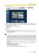
15 Configuring the network settings [Network] • • When the camera access is open to the Internet, enter the address name or host name to access via the Internet for “Common Name”. In this case, the security alert window will be displayed each time the camera is locally accessed, even if the security certificate is installed. When the security certificate is properly installed, a key icon is displayed in the address box of the web browser that has accessed the camera.
15 Configuring the network settings [Network] 3. Click “Certificate Error” over the URL, and click “View certificates”.
15 Configuring the network settings [Network] 4. Click “Install Certificate...”. Note • 122 If [Install Certificate...] is not displayed, close Internet Explorer once, and select [Run as Administrator] to launch Internet Explorer again. Click [Start] ® [All Programs] ® right click [Internet Explorer] ® click [Run as Administrator].
15 Configuring the network settings [Network] 5. Click “Next” displayed on “Certificate Import Wizard”. 6. Select “Place all certificates in the following store”, and click “Browse...”.
15 Configuring the network settings [Network] 7. Select “Trusted Root Certificate Authorities”, and click “OK”. 8. Click “Next”.
15 Configuring the network settings [Network] 9. Click “Finish”. 10. Click “Yes”. → When the import is successfully completed, the screen “The import was successful.” will be displayed.
15 Configuring the network settings [Network] 11. Click “OK”. → When the browser is restarted after the certificate is imported, “Certificate Error” will not be displayed. OS: Windows XP, Web browser: When using Internet Explorer 6 1. Access the camera using the HTTPS protocol. 2. Click “View Certificate”. Note • 126 If this window is displayed when accessing a device other than the camera or a website, a security problem may have occurred. In this case, check the system status.
15 Configuring the network settings [Network] 3. Click “Install Certificate...”. 4. Click “Next >” according to the procedures displayed on the displayed on “Certificate Import Wizard”.
15 Configuring the network settings [Network] 5. Click “Finish”.
15 Configuring the network settings [Network] 6. When the security alert window is displayed, click “Yes”. → When the import is successfully completed, the screen “The import was successful.” will be displayed. 7. Click “OK”. → When the browser is restarted after the certificate is imported, “Certificate Error” will not be displayed. 15.4 Configure the settings relating to DDNS [DDNS] Click the [DDNS] tab on the “Network” page.
15 Configuring the network settings [Network] It is possible to configure the settings for the “Viewnetcam.com” or Dynamic DNS Update (RFC2136 compliant). In most of the DNS services offered by providers, global addresses are not static but dynamic. Therefore, access to the camera via an old global address may be invalidated after a certain period of time. Either of the following services is required when accessing a camera whose global address is not static via the Internet.
15 Configuring the network settings [Network] Global address is obtained via the URL (domain name). By entering the URL (including the domain name) on the web browser when accessing the camera via the Internet, the DNS server identifies the registered global address of router (or camera). Access using the current global address The identified global address is used for accessing the router (or camera) to monitor images.
15 Configuring the network settings [Network] [Access interval] Select the interval to access the “Viewnetcam.com” service server to check the IP address and the host name from the following. 10min/ 20min/ 30min/ 40min/ 50min/ 1h • Default: 1h 15.4.3 Procedure to register information for the “Viewnetcam.com” service 1. Select [Viewnetcam.com] for [DDNS] and click the [Set] button. → A URL is displayed in [Your Account Link].
15 Configuring the network settings [Network] • • • When “Expired” is displayed in the URL of “Viewnetcam.com” in the viewnetcam settings page or the status page, restart the camera after registering the “Viewnetcam.com” service. After restarting the camera, check that the registered URL is displayed in the URL of “Viewnetcam.com” of [Status] [Viewnetcam.com] on the “Maintenance” page. It is possible to check the information registered for the “Viewnetcam.
15 Configuring the network settings [Network] 15.4.6 When using “Dynamic DNS Update(DHCP)” [Host name] Enter the host name to be used for the Dynamic DNS Update service. • Available number of characters: 3 - 250 characters Enter in the form of “(host name). (domain name)”. • Available characters: Alphanumeric characters, the colon (:), the period (.), the underscore (_), and the hyphen (-).
15 Configuring the network settings [Network] • • Available number of characters: 0 - 32 characters Default: None (blank) [Location] Enter the name of the location where the camera is installed. • Available number of characters: 0 - 32 characters • Default: None (blank) [Contact] Enter the E-mail address or the phone number of the SNMP manager. • Available number of characters: 0 - 255 characters • Default: None (blank) 15.
15 Configuring the network settings [Network] [FTP periodic image transmission] Select “On” or “Off” to determine whether or not to transmit images using the FTP periodic image transmission function. When “On” is selected, it is necessary to configure the settings of the FTP server. (®page 100) • Default: Off [Directory name] Enter the directory name where the images are to be saved. For example, enter “/img” to designate the directory “img” under the root directory of the FTP server.
15 Configuring the network settings [Network] 15.7 Configure the schedule settings of the FTP periodic image transmission [FTP img. trans.] Click the [FTP img. trans.] tab on the “Network” page. (®page 34, page 35) The schedule settings of the FTP periodic image transmission can be configured in this section. Refer to page 135 for further information about the settings relating to the FTP periodic image transmission. 15.7.1 How to set the schedules 1.
15 Configuring the network settings [Network] 3. Click the [Set] button after completing the settings. → The result will be displayed at the bottom of the window. 15.7.2 How to delete the set schedule 1. Uncheck the check box of the set day of the week.
15 Configuring the network settings [Network] 2. Click the [Set] button after completing the settings. → The schedule of the selected day of the week is deleted.
16 Use the camera on a wireless LAN [Wireless] (BL-VT164W/BL-VP104W) 16 Use the camera on a wireless LAN [Wireless] (BL-VT164W/BL-VP104W) Wireless network settings for connecting the camera to a wireless router or other wireless device can be configured on the “Wireless” page. The “Wireless” page has 2 tabs; the [Basic] tab and the [Status] tab. Complete the network settings with a wired connection using a LAN cable before performing wireless settings.
16 Use the camera on a wireless LAN [Wireless] (BL-VT164W/BL-VP104W) The wireless settings can be manually configured to the camera in this section, and the camera can be connected to the wireless network. 1. Check the wireless router's setting information. • Check the SSID and wireless security settings configured to your wireless router, and whether MAC address filtering is activated or deactivated. If MAC address filtering is activated, register the camera’s MAC address to the wireless router.
16 Use the camera on a wireless LAN [Wireless] (BL-VT164W/BL-VP104W) • Default: 802.11n/b/g [ShortGI enabled] 3. Set each item of the [Wireless: Encryption settings] in accordance to the encryption method used. WEP method WPA-PSK (TKIP), WPA-PSK (AES), WPA-PSK (TKIP/AES), WPA2-PSK (TKIP), WPA2-PSK (AES), WPA2-PSK (TKIP/AES), or WPA/WPA2-mixedmode PSK method [Encryption method] Select the encryption method for the data to be transmitted.
16 Use the camera on a wireless LAN [Wireless] (BL-VT164W/BL-VP104W) • • • • • 5 alphanumeric characters: 64bit Example: 012yz 13 alphanumeric characters: 128bit Example: 0123456uvwxyz Available number of characters: 10 or 26 characters (10 hex characters: 64bit/26 hex characters: 128bit)/5 or 13 characters (5 alphanumeric characters: 64bit/13 alphanumeric characters: 128bit) Available characters: 0 - 9, A - F or a - f (10 hex characters: 64bit/26 hex characters: 128bit)/ alphanumeric characters (5 alphan
16 Use the camera on a wireless LAN [Wireless] (BL-VT164W/BL-VP104W) • Depending on the network environment and the wireless devices used (2.4 GHz cordless telephones/faxes or other wireless LAN devices), transmission speeds may become slower. 16.2 Connecting the camera to a wireless LAN with WPS (automatic settings) [Basic] First, confirm that “Enable” (default setting) is set for “External registration” in “Wi-Fi Protected Setup (WPS)”. Click the [Basic] tab on the “Wireless” page.
16 Use the camera on a wireless LAN [Wireless] (BL-VT164W/BL-VP104W) 1. Turn on the camera without connecting the LAN cable to enable the wireless settings. → After the initial pan/tilt operations are performed, the POWER indicator stops blinking orange and lights orange. The POWER indicator lights orange and the camera starts up in wireless LAN mode about 90 seconds after the camera was turned on. 2. Select ON for the WPS function (Push-button method (PBC)) on the wireless router.
16 Use the camera on a wireless LAN [Wireless] (BL-VT164W/BL-VP104W) 3. Configure [Wi-Fi Protected Setup (WPS)]. – – – • • • Select “Enable” for “External registration”. (Default: Enable) Select “Use” for “WPS compliant (PIN method)”. (Default: Not use) Enter the wireless router's 8 digit PIN code in the “PIN code” field.
16 Use the camera on a wireless LAN [Wireless] (BL-VT164W/BL-VP104W) 2. Configure [Wi-Fi Protected Setup (WPS)]. – – – • • • Select “Enable” for “External registration”. (Default: Enable) Select “Use” for “WPS compliant (PIN method)”. (Default: Not use) Click the [Generate] button or [Default] button to set the “PIN code”. Available number of characters: 8 characters Available characters: Numbers Default: None (blank) Note • • • The [Generate] button of “PIN code” generates a random 8 digit PIN code.
16 Use the camera on a wireless LAN [Wireless] (BL-VT164W/BL-VP104W) IMPORTANT If the wireless settings failed to be automatically set with WPS, check the wireless settings for the wireless router and camera in the following manner. Checking wireless settings for the wireless router • If the wireless setting of the wireless router is set to a setting not supported by the camera, change the wireless setting of the wireless router. • Confirm that the WPS function is activated.
16 Use the camera on a wireless LAN [Wireless] (BL-VT164W/BL-VP104W) Note • The screen is refreshed in 10 seconds intervals periodically to monitor the radio wave status. This may cause the screen to flicker. [Wireless module status] Displays the current status of the wireless module. [Firmware version (Wireless)] Displays the wireless firmware version of the camera. [Operation mode] Displays the camera's operation mode (Wired or Wireless).
16 Use the camera on a wireless LAN [Wireless] (BL-VT164W/BL-VP104W) [BSSID] Displays the connected wireless router's MAC address. When a wireless router is not connected, “00-00-00-00-00-00” is displayed. [Authentication method] Displays the authentication method (Open System, WPA-PSK, or WPA2-PSK) in accordance to the currently selected encryption method. [Encryption method] Displays the currently selected encryption method (WEP, TKIP, or AES).
17 Configure the settings relating to the schedules [Schedule] 17 Configure the settings relating to the schedules [Schedule] On the “Schedule” page, it is possible to configure the settings relating to schedules as follows. • Alarm permission (Alarm input will be received only in the specified schedule.) • VMD permission (Video motion detection will be active only in the specified schedule.
17 Configure the settings relating to the schedules [Schedule] 1. Select an action to be assigned to the schedule from “Schedule mode”. “Off” is selected at the default. • Off: No action will be taken for the respective schedule. • Alarm permission: Alarm input (terminal alarm) will be received during the period of the schedule. • VMD permission: The video motion detection (VMD) function will be active during the period of the schedule.
17 Configure the settings relating to the schedules [Schedule] • • • VT164 : The body heat sensor detection will be active Body heat sensor permission VT164W during the period of the schedule. Access permission: Users whose access level is set to 2 and 3 on the “User auth.” tab (®page 94) can access the camera only in the period of schedule. VT164 : The camera will move to the designated preset position at the designated 1-64 VT164W time in the schedule. Note • Select “On” for “User auth.
18 Maintenance of the camera [Maintenance] 18 Maintenance of the camera [Maintenance] System log check, firmware upgrade, status check and initialization of the setup menu can be performed on this page. The “Maintenance” page has 4 tabs; the [System log] tab, the [Upgrade] tab, [Status] tab and the [Default reset] tab. 18.1 Check the system log [System log] Click the [System log] tab of the “Maintenance” page. (®page 34, page 35) Up to 100 system logs can be saved on the built-in memory of the camera.
18 Maintenance of the camera [Maintenance] The current firmware can be checked and upgraded to the latest version on this page. Contact the dealer for further information about the firmware upgrade. [Model no.], [MAC address], [Serial no.], [Firmware version], [IPL version], [HTML version], [IP address(IPv6)], [Viewer software installation counter] Information of each item will be displayed. 1. Contact the dealer and download the latest firmware onto a PC.
18 Maintenance of the camera [Maintenance] IMPORTANT • • • • After completing the upgrade, delete temporary internet files. (®page 170) Upgrade the firmware using a PC in the same subnet as the unit. Follow the instructions from the dealer when upgrading the firmware. When upgrading the application software, use the designated file (extension: img) for the firmware upgrade. The name of the firmware to be used for the upgrade should be “model name (Use small letters. “BL-” is not required.)_xxxxx.img”.
18 Maintenance of the camera [Maintenance] The status of this camera can be checked on this page. [Viewnetcam.com] • Server: The URL of the “Viewnetcam.com” service server will be displayed. • Status: The registration status for the “Viewnetcam.com” will be displayed. • Personal(Camera) URL: The URL of the camera registered for “Viewnetcam.com” will be displayed. [UPnP] • Port number(HTTP), Port number(HTTPS): The port number that is set for UPnP port forwarding will be • • displayed.
18 Maintenance of the camera [Maintenance] The settings and the HTML data of the camera can be initialized and reboot of the camera can be performed on this page. [Reset to the default (Except the network settings)] Click the [Execute] button to reset the settings to the default. Note that the network and wireless*1 settings will not be reset. It is impossible to operate the camera for about 3 minutes after the initialization. [Load the default HTML files (setup menu).
19 Privacy Mode (BL-VT164W/BL-VT164) 19 Privacy Mode (BL-VT164W/BL-VT164) Privacy mode allows you to protect your privacy by hiding the lens inside the camera, preventing camera images from being seen. When privacy mode is activated: – The POWER indicator turns red so that you can easily see that privacy mode is activated. – The live image changes to a black display. – JPEG images attached to “Alarm image” transfers, “FTP img. trans.” transfers, and “E-mail” transfers change to black images.
19 Privacy Mode (BL-VT164W/BL-VT164) 19.2 Configuring the Privacy Mode with the setup menu 1. Click the [Privacy] button in the setup menu. → The lens will be hidden in the top part of the camera and the POWER indicator will light. 19.3 Turning the Privacy Mode off You can turn privacy mode off by: – Pressing the camera’s PRIVACY button (the POWER indicator will turn from red to green). – Accessing the camera with a PC.
20 Using the CD-ROM 20 Using the CD-ROM 20.1 About the CD launcher By inserting the provided CD-ROM into the CD-ROM drive of your PC, the CD launcher is automatically started and the license agreement is displayed. Read the agreement and select “I accept the terms in the license agreement”, and then click “OK”. • If the launcher window is not displayed, double click the “CDLauncher.exe” file on the CD-ROM. A B C D E Using the supplied CD-ROM, the following actions can be performed.
20 Using the CD-ROM 20.2 Installing Panasonic “IP Setting Software” On the CD launcher window, click the [Install] button next to [IP Setting Software] to display the Panasonic “IP Setting Software” installation window. Confirm the following settings before starting the installation. A B C D Select the Panasonic “IP Setting Software” to install. Select where to create the Panasonic IP setting shortcut icon when the Panasonic “IP Setting Software” is installed.
20 Using the CD-ROM 20.3 Installing the manuals On the CD launcher window, click the [Install] button next to [Manual] to display the Manual installation window. Confirm the following settings before starting the installation. A B C D E Select which manuals to install. The camera models that the manuals support are displayed in B “Model List”. The camera models that are supported by the manuals selected in A are displayed here.
20 Using the CD-ROM 20.5 Configure the network settings of the camera using the Panasonic “IP Setting Software” It is possible to perform the network settings of the camera using the “IP Setting Software” on the provided CD-ROM. When using multiple cameras, it is necessary to configure the network settings of each camera independently. If the Panasonic “IP Setting Software” does not work, configure the network settings of the camera and the PC individually on the “Network” page of the setup menu.
20 Using the CD-ROM 3. Complete each network setup item and click the [Save] button. • For further information about each setting of the “Network Settings” page, refer to page 104. Note • By unchecking the “Wait for camera restarting.” checkbox, multiple cameras can be continuously configured. IMPORTANT • • It may take for around 2 minutes to complete to upload the settings to the camera after clicking the [Save] button.
21 About the displayed system log 21 About the displayed system log Error indications relating to SMTP Category POP3 server error Indication Description Authentication error. • Entered user name or password may be incorrect. Check if the E-mail settings are configured correctly. Failed to find the POP3 server. • The IP address of the server may be incorrect. Check if the IP address of the server is configured correctly. The POP3 server may be down. Ask the network administrator.
21 About the displayed system log Category Internal error Indication Undefined error. Description • An error occurred in the FTP function. Check if the FTP settings are configured correctly. Error indications relating to “Viewnetcam.com” Category Viewnetcam.com server error Indication Failed to resolve the Viewnetcam.com server address from DNS. Description • • Connection error No response from the Viewnetcam.com server. The designated IP address of the DNS may be incorrect.
21 About the displayed system log Error indications relating to NTP Category Connection error Indication No response from the NTP server. Description • • The IP address of the server may be incorrect. Check if the IP address of the server is configured correctly. The NTP server may be down. Ask the network administrator. Internal error Undefined error. • An error occurred in the NTP function. Check if the NTP settings are configured correctly. Synchronizing with NTP succeeded.
21 About the displayed system log Error indications relating to Panasonic alarm protocol notification Category Panasonic alarm protocol notification error Indication Failed to find destination of notification. Description • • Cannot resolve notification addresses from DNS • • The IP address of the destination of notification may be incorrect. Check if the IP address of the destination of notification is configured correctly. The destination of notification may be down. Ask the network administrator.
22 Troubleshooting 22 Troubleshooting Before asking for repairs, check the symptoms with the following table. Contact your dealer if a problem cannot be solved even after checking and trying the solution in the table or a problem is not described below. Symptom Cannot access from the web browser. Cause/solution • Is the LAN cable (category 5) firmly connected to the network connector of the camera? Installation Guide • Is the power of the camera on? Check if the power of the camera is turned on.
22 Troubleshooting Symptom Cannot access from the web browser. Cannot access the camera via the Internet.
22 Troubleshooting Symptom Cause/solution Reference pages • Are you accessing the camera using the local address (the IP address used in a local network)? When accessing the camera, use the global address (or the URL registered in the DDNS service) and the port number of the camera as the IP address to be used in the Internet. 105 106 129 Cannot access the camera via the URL of the “Viewnetcam.com” service. • Is the global address of camera (or router) notified to the “Viewnetcam.
22 Troubleshooting Symptom Cause/solution Reference pages • Is the SSL encryption method different from that of the camera? Select “HTTP” (Do not select “HTTPS”) for “HTTPS” - “Connection” on the “Network” page - the [Network] tab, and access the camera again. 104 • Did you access “http://” while using the HTTPS function? To use the HTTPS function, access “https://”. It is also necessary to enter the port number.
22 Troubleshooting Symptom Cause/solution Reference pages • Is the cellular phone in use support the 320´240 resolution? Or is the image data size too big to display images on the cellular phone? Refer to the manuals provided with the cellular phone in use for the restrictions of image data sizes. - No image is displayed. / Older images or logs are displayed.
22 Troubleshooting Symptom Cause/solution Reference pages The camera does not move onto the preset position exactly. • Is any part of the camera worn out? When the camera does not move to the exact position frequently, the driving parts may be worn out. Contact the dealer for assistance. The camera does not automatically move to the previous position when turning on the power of the camera.
22 Troubleshooting Symptom Cause/solution Reference pages H.264 images are not displayed. • When “Network Camera View 4S” is deleted from a PC on which both the viewer software “Network Camera View 3” and “Network Camera View 4” are installed, H.264 images may not be displayed. In this case, delete “Network Camera View 3” from the PC and then install “Network Camera View 4S”. 3 When displaying H.
22 Troubleshooting Symptom Cannot connect to the wireless router VT164W Reference pages • Is the camera in an area with no wireless signal, or is there a concrete wall or other obstructions between the camera and wireless router? Check the [Radio wave status] from [Wireless] [Status] on the setup menu, and install the camera in an area that is close to the wireless router, has no interfering objects, and can easily receive signals.
22 Troubleshooting Information Bar Depending on the OS installed on the PC, the following may occur. Follow the instructions below when the following has occurred. By performing the following solutions, other applications may not be affected. When using Internet Explorer 9.0: The “Information Bar” (A) expressed in the following symptom and solutions will be displayed on the lower side of the Internet Explorer page only when there is information to communicate. A When using Internet Explorer 6.
22 Troubleshooting Symptom Cause/solution Reference pages The following message is displayed on the information bar. “This webpage wants to install the following add-on: `nwcv4Ssetup.exe' from `Panasonic System Networks Co.,Ltd.`.” (Internet Explorer 9) • Select [Install]. The “Security Warning” window will be displayed. Click the [Install] button on the displayed “Security Warning” window. - An unnecessary status bar or scroll bar is displayed on the pop-up window. • Click “Internet Options...
For U.S. and Canada: Panasonic System Communications Company of North America, Unit of Panasonic Corporation of North America www.panasonic.com/business/ For customer support, call 1.800.528.6747 Three Panasonic Way, Secaucus, New Jersey 07094 U.S.A. Panasonic Canada Inc. 5770 Ambler Drive, Mississauga, Ontario, L4W 2T3 Canada (905)624-5010 www.panasonic.ca For Europe and other countries: http://panasonic.