Panasonic Broadcast BT-LT80W Menu Information
How to Use the On Screen Menu Six types of information are displayed on the screen: the operating status display, picture adjusting knob status, sharpness display, function display, DC power supply voltage display, battery level display and menu display. Operating status display 1 7 6 2 YPBPR 1080/60I P-P DC14.0V 5 4 50% 3 1. The selected input line (→ page 7, 2 ) • YPBPR, VF-YPBPR/VF-VIDEO, VIDEO, SDI 2.
How to Use the On Screen Menu (continued) Sharpness display • SHARPNESS H/V is displayed when it is set. • The display disappears if remains idle for 2 minutes. SHARPNESS H 30 Function display F1:MARKER F2:WFM F3:PIXEL TO PIXEL XXXXX • You can set FUNCTION display in the menu. • When “FUNCTION DISPLAY” (→ page 23) is ON1 or ON2 and one of the buttons from [FUNCTION1] to [FUNCTION3] is pressed, the unit displays the status of the FUNCTION item that is set.
How to Use the On Screen Menu (continued) Menu operations 1. Push [MENU] to display the MAIN menu. ] to select the sub menu, then push 3. Push [ , [ENTER]. The setting values in the sub menu change to green. FUNCTION 1 INPUT 2. Push [ , [ENTER]. MENU 2 3 ENTER ] to select the menu, then push [MAIN MENU] MARKER VIDEO CONFIG SYSTEM CONFIG VF CONFIG FUNCTION GPI INPUT SELECT CONTROL HOURMETER MENU EXIT SEL. ENTER ENTER To return to the previous screen Push [MENU].
User Data You can change the menu setting values and picture adjusting knob settings, then save and load up to 5 combinations of screen adjustment values as user data. You can also return the setting values and adjustment values to the factory preset settings. The following settings are included in user data.
Main Menu Menu configuration MAIN MENU MARKER MARKER 16:9 VIDEO CONFIG SYSTEM CONFIG COLOR TEMP. 4:3 CONT./BACK.
Main Menu (continued) MARKER The underlined values are factory preset setting values. Sub menu MARKER Settings OFF∗1 ON Explanation Used to make MARKER settings effective. 16:9∗2∗3 OFF 4:3 13:9 14:9 CNSCO VISTA 95% 93% 90% 88% 80% Used to select/display the type of marker when the aspect ratio setting is 16:9. Marker not displayed.
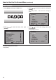
Main Menu (continued) Types of MARKER 16:9 marker (Displayed when using HD, or when using SD with a 16:9 aspect ratio) The marker is only displayed as a vertical bar. In section becomes the “MARKER addition, the BACK” item. 4:3 marker 4:3 marker (Displayed when using SD with a 4:3 aspect ratio) A dotted line is displayed as the marker.
Main Menu (continued) VIDEO CONFIG The underlined values are factory preset setting values. Sub menu Settings Explanation COLOR TEMP. USER 63∗1 D93 D65 D56 VAR1 VAR2 VAR3 Used to select the color temperature.
Main Menu (continued) About IP Mode By selecting “MODE1”, you can convert IP through Frame Interpolation. This unit has reduced the Frame Interpolation delay to 1 field or less, compared to our old models having caused 1 frame delay or more. Factory preset setting value is “MODE1” recommended for normal use. Depending on images, in very rare cases, noise may occur on the screen. In such a case, “MODE 2” is recommended. By selecting “MODE2”, you can convert IP through Field Interpolation.
Main Menu (continued) SYSTEM CONFIG The underlined values are factory preset setting values. Sub menu Settings Explanation CONT. /BACK. BACKLIGHT CONTRAST Used to select the function to be assigned to CONT/B.LIGHT (a knob on the front panel). Used to adjust BACKLIGHT. Used to adjust CONTRAST. BACKLIGHT 0 - 60 Used to adjust the LCD backlight level. CONT./BACK displays “-” while BACKLIGHT settings are performed.
Main Menu (continued) VF CONFIG The underlined values are factory preset setting values. Sub menu Settings Explanation VF CONTROL VF-CH ALL-CH Used to select the input line for the VF function of the monitor. (VF function: tally lamp lit, zebra displayed, displayed) Only enabled when the VF line is selected. Enabled with all input lines. CROSS HATCH HIGH LOW OFF Used to set whether to display a cross hatch and select its density level.
Main Menu (continued) FUNCTION The underlined values are factory preset setting values. Sub menu Settings Explanation FUNCTION1 - 3 BLUE ONLY SD ASPECT∗1∗2 WFM MARKER∗1∗3 PIXEL TO PIXEL∗4 PIXEL POS.+∗5 PIXEL POS.–∗5 FOCUS-IN-RED ∗4∗7 ZEBRA REAR TALLY∗6 CROSS HATCH MONO∗1 UNDEF Used to select the functions to be assigned to individual buttons [FUNCTION1] to [FUNCTION3] (front-panel buttons). Used to cut the red and green signals. You can check the hue (PHASE) and depth of color (CHROMA).
Main Menu (continued) Restrictions on various FUNCTION settings Under the following conditions, various settings are disabled. Setting Disabling condition SD ASPECT Does not operate while GPI items are being set. Does not operate during PIXEL TO PIXEL operation. Does not operate during HD display. If operated during the conditions described above, “INVALID FUNCTION” is displayed. WFM Does not operate during PIXEL TO PIXEL or FOCUS-IN-RED mode.
Main Menu (continued) About WFM You can display the wave form monitor using the “WFM” function. The display changes each time you press one of the buttons, [FUNCTION1] to [FUNCTION3] (→ page 23), assigned with the [WFM] function (To use the “WFM” function, you must assign it to one of the [FUNCTION1] to [FUNCTION3] buttons). Press the FUNCTION button assigned with the WFM function once. Normal window WFM display Press the same button again. WFM (Wave Form Monitor) The window is displayed in 16:9 aspect.
Main Menu (continued) Display position sequence during an HD signal 1080i input PIXEL POS.+: 1)→2)→3)→4)→5)→6)→7)→8)→9)→1) · · · · · PIXEL POS.–: 1)→9)→8)→7)→6)→5)→4)→3)→2)→1) · · · · · 1) CENTER 2) LEFT TOP 3) MID TOP 4) RIGHT TOP 5) RIGHT MID 6) RIGHT BOTTOM 7) MID BOTTOM 8) LEFT BOTTOM 9) LEFT MID Display position sequence during an HD signal 720P input PIXEL POS.+: 1)→2)→3)→4)→5)→1) · · · · · PIXEL POS.
Main Menu (continued) About FOCUS-IN-RED When the FOCUS-IN-RED function is used, the section that is being focused is displayed in an easy-to-understand red, making camera focus adjustments easy. Each time the button from [FUNCTION1] to [FUNCTION3] to which the FOCUS-IN-RED function is assigned is pushed, the display is switched (the FOCUS-IN-RED function must be assigned to one of the buttons from [FUNCTION1] to [FUNCTION3] in order to be able to use the FOCUS-IN-RED function).
Main Menu (continued) GPI The “GPI CONTROL” item is used to set enable/disable of all GPI functions, and assigns functions to each of the GPI terminal pins (→ page 31). The underlined values are factory preset setting values. Sub menu Settings Explanation GPI CONTROL DISABLE ENABLE GPI functions enable/disable settings Deactivate Activate GPI1 - GPI8 UNDEF MARKER1 ON/OFF MARKER2 ON/OFF MARKER BACK HALF MARKER BACK BLACK CENTER MARKER INPUT SEL. YPBPR INPUT SEL. VF INPUT SEL.
Main Menu (continued) INPUT SELECT The underlined values are factory preset setting values. Sub menu Settings Explanation YPBPR ON OFF Used to set the YPBPR line to the INPUT SELECT button.∗1 COMPONENT LEVEL SMPTE B75 B00 Used to select the input level for the YPBPR (component) signal. When the signal level specified in SMPTE is Chroma 100 IRE, PB, PR=0.7Vp-p Select this when connecting a betacam or similar devices with a 7.5 IRE setup level.
Main Menu (continued) CONTROL The underlined values are factory preset setting values. Sub menu Settings Explanation CONTROL LOCAL REMOTE Used to select the operation. (Combined control lock) Front operation enabled Remote operation enabled (The front controls become locked)∗1 LOCAL ENABLE DISABLE INPUT When “REMOTE” is selected in “CONTROL”, this selects whether front controls are enabled/disabled. All front operations are disabled.