Operating Instructions Version 1.1 Network Camera Management System Model No. BB-HGW700A Please read this manual before using and save this manual for your future reference. Panasonic Web Site: http://www.panasonic.
Operating Instructions Introduction Thank you for purchasing the Panasonic Network Camera Management System. Before using Please read the Important Safety Instructions on page 4 before using. Read and understand all instructions. For Operation Assistance • Call 1-800-272-7033 • See the Panasonic web site http://www.panasonic.
Operating Instructions Abbreviations • UPnP is the abbreviation for Universal Plug and Play. • CATV modems and ADSL modems are referred to as modems in this manual. • Network cameras are referred to as cameras in this manual. Trademarks • Microsoft, MSN, Windows and DirectX are either registered trademarks or trademarks of Microsoft Corporation in the United States and/or other countries. • Screen shots reprinted with permission from Microsoft Corporation.
Operating Instructions IMPORTANT SAFETY INSTRUCTIONS When using this product, basic safety precautions should always be followed to reduce the risk of fire, electric shock, or personal injury. 1. 2. 3. 4. 5. Read and understand all instructions. 6. Protect the AC adaptor cord and AC cord from being walked on or pinched particularly at plugs, convenience receptacles, and the point where they exit from this product. 7.
Operating Instructions Table of Contents 1 Product Introduction ............................................................. 7 1.1 Main Features ........................................................................................ 7 1.2 Included Accessories............................................................................. 8 1.3 Feature Locations .................................................................................. 9 1.3.1 Front View ..............................................
Operating Instructions • Routing ............................................................................................................................... 86 3.2.6 Using VPN (PPTP).............................................................................................88 3.2.7 Using VPN (IPsec) .............................................................................................90 3.2.8 Using Applications....................................................................................
Operating Instructions Product Introduction 1.1 Main Features This product is a Network Camera Management System with the following features: ■ IPv6 Compatible This product is compatible with IPv6, the next generation of Internet protocol. There are a number of merits to this, such as, abundant global addresses and security improvement through using IPsec. ■ Camera Privacy Protection with VPN This product is compatible with PPTP (IPv4) and IPsec (IPv4/IPv6) for VPN.
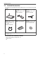
Operating Instructions 1.2 Included Accessories The following items are provided with this product. Additional pieces can be ordered by calling 1-800332-5368. Main unit ........................1 pc. AC adaptor..................... 1 pc. (Cord length: approx. 3 m (9.8 feet)) Order No. PQLV202Y AC cord ......................... 1 pc. (Cord length: approx. 1.8 m (5.9 feet)) Order No. PSJA1069Z Ethernet® cable (category 5 straight cable).................1 pc. (Cable length: approx. 1 m (1.
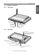
Operating Instructions 1.3 Product Introduction 1.3.1 Feature Locations Front View POWER Indicator (see page 10) WAN Indicator (see page 10) PPPoE Indicator (see page 10) 1.3.2 WIRELESS Indicator (see page 10) LAN1-LAN4 Indicators (see page 10) Rear View Diversity Antenna The antenna rotates 100 degrees clockwise and counterclockwise, 200 degrees in total.
Operating Instructions 1.3.3 Indicators Indicators Light Color POWER Description This product is turned on. Green Red (Blinking) Green (Blinking) WAN Green There is a problem with this product. Remove the AC cord from the outlet, and insert again. The firmware is damaged. Download a firmware file (see page 31 - Installation/ Troubleshooting). This product is successfully connected to a modem or an Ethernet hub etc. This product is connected and sending or receiving data.
Operating Instructions 2 Accessing This Product 2.1 Functions 2.1.1 Top Page The top page allows you to select the Setup page or Camera Portal page. The Camera Portal page displays the images of the camera connected to this product. Enter "http://bbhgw.webpage:8080" into the web browser's address bar. (The default port number is 8080.) • The user name and password window is displayed. 2. Enter New User Name, New Password, and Retype New Password and click [Save]. • The top page is displayed.
Operating Instructions Setup (see page 13) Camera Portal (see page 17) Notes • In the default settings, it is possible to display the top page by entering "http://192.168.0.254:8080" into the web browser's address bar. • When accessing Setup from the top page, an authentication window is displayed (after starting the web browser, first time only). Log in by entering your user name and password and clicking [OK].
Operating Instructions 2.1.2 Setup This page allows you to set up an IPv4 Internet connection using your PC's web browser. The heading selected on the menu page is displayed on the main page. The help page describes the operations of each heading. Accessing This Product 1 2 3 4 5 6 7 8 9 10 11 12 13 14 15 16 17 18 19 20 21 22 23 24 25 26 27 Menu Main 1 Top: Displays the top page. (see page 11) 2 Setup: Displays the setup page. It is possible to set up all operations from this page.
Operating Instructions Basic Setup 5 ISP Registration: Basic setup to connect to the Internet. (see page 22) 6 Connection Mode: Sets the connecting ISP. (see page 38) 7 Camera: Performs automatic camera registration setup and manual registration adding and deletion. (see page 40) 8 Wireless: Sets up wireless LAN motion mode and wireless security. (see page 48) 9 DynamicDNS Sets up DynamicDNS.
Operating Instructions Information Displays information such as connection status. (see page 109) 25 Log: Displays Filtering Log, UPnP Log (general), UPnP Log (CP), Connection Log, DynamicDNS Log, VPN (PPTP) Connection Log, VPN (IPsec) Connection Log, Mail Transmission Log, and VPN (IPv4 IPsec) Connection Log. (see page 112) 26 Support: Product and support information can be found on the Internet. (see page 116) 27 Help: Explains about commands and functions on the setup pages.
Operating Instructions 2.1.3 IPv6 Setup This page allows you to set up an IPv6 Internet connection using your PC's web browser. The heading selected on the menu page is displayed on the main page. The Help page describes the operations of each heading. 1 2 3 Menu 16 Main 1 IPv6 ISP Registration: IPv6 basic setup to connect to the Internet. (see page 30) 2 IPv6 Security: Allows you to set up IPv6 filtering, and control access to this product at the touch of button, and automatically saves a log.
Operating Instructions 2.1.4 Camera Portal This product has a built in web server function. Camera Portal allows you to list up to 16 cameras names and their still images. Viewing Camera Images from the LAN (Home) Side It is possible to view camera images by accessing the camera portal. Start the web browser. 2. Enter "http://bbhgw.webpage:port number" into the web browser's address bar. • (e.g. http://bbhgw.webpage:80 The default port number is 80.
Operating Instructions • 3. If the camera and this product are disconnected while sending or receiving data, a key mark (when camera authentication is set up) or a blue unmarked window is displayed. In this case, after checking that the camera's power supply and connections are correctly inserted, click [Refresh Camera]. Click the camera frame you want to access. • If an authentication window is displayed, enter the camera's user name and password. Then the camera image is displayed.
Operating Instructions Viewing Camera Images from the WAN (Internet) Side This function allows you to view camera images by accessing the camera portal from the WAN side. Note To view camera images from the Internet, it is necessary to connect this product to your modem and have an Internet subscription. Regarding how to connect to the Internet see Installation/ Troubleshooting and Using the Functions (see page 22). 1. 2. Start the web browser.
Operating Instructions • If an exclamation mark is displayed, click it and the camera's password window is displayed. Perform the settings on each page. Setting Allow Access from the Internet to Enable, displays the camera images on the Camera Portal over the Internet. Setting Disable only displays the camera images on the Camera Portal when accessing from the LAN side. (It is displayed when a factory default camera is connected.
Operating Instructions If the camera portal is not displayed... • Check that "http:// IP address(WAN) or URL : port number" was entered correctly into the address bar. • Sometimes it is necessary to set up the web browser's proxy server to access the website. (see page 131) • When a camera name, an X mark, or a white page is displayed on the camera portal, click [Refresh Camera].
Operating Instructions 3 Functions 3.1 Using the Functions 3.1.1 Registering ISPs The ISP registration page allows you to register new ISPs (see page 23) for this product, edit them, and delete them (see page 29). Internet connection methods vary according to the ISP. Select a connection method referring to the ISP's setup information. Consult with your contracted ISP about which connection type to use, or about your service or contract.
Operating Instructions PPPoE Connection Follow the steps below to set up PPPoE connection. Private address 192.168.0.2 ISP Modem Internet The ISP assigns an IP address by PPPoE connection. Private address 192.168.0.1 Select [ISP Registration]. 2. Click [Register/Edit] on the ISP registration list. 3. Select PPPoE. [For assistance, please call: 1-800-272-7033] Functions 1.
Operating Instructions 4. Enter ISP Name. • Enter no more than 20 characters. In the example right, "abcde" has been entered. 5. Enter User Name and Password, and if specified by the ISP, enter Service Name, Access Concentrator Name, DNS Server 1, 2, and/or Domain Name. • See the ISP's setup information. To return to the original settings, click [Cancel]. 6. When setup is complete, click [Save and Go to Connection Mode]. • The connection mode page is displayed. 7. Select the ISP entered in step 4.
Operating Instructions DHCP Connection (Internet Connection using a DHCP Server) Follow the steps below to set up DHCP connection, where an IP address is automatically allocated by the ISP. ISP Modem Private address 192.168.0.2 Internet The ISP's DHCP Server assigns an IP address. Private address 192.168.0.1 Select [ISP Registration]. 2. Click [Register/Edit] on the ISP registration list. 3. Select DHCP. 4. Enter ISP Name. • Enter no more than 20 characters.
Operating Instructions 6. When setup is complete, click [Save and Go to Connection Mode]. • The connection mode page is displayed. 7. Select the ISP entered in step 4. 8. When setup is complete, click [Save]. • The entered information is saved. Note When saving, do not cut the power supply. If cut, saving might not be completed successfully. 9. When [Restart] is displayed on the setup page, click it. 10. Restart the PC. • Check that the PC is connected to the Internet.
Operating Instructions Static Connection (Internet Connection using a Static IP Address) It may be necessary, if you are instructed by the ISP, to enter the value of the IP address or gateway address into setup information. Private address 192.168.0.2 ISP Modem Internet Static IP Address An IP address is set based on information from the ISP. Private address 192.168.0.1 Select [ISP Registration]. 2. Click [Register/Edit] on the ISP registration list. 3. Select Static.
Operating Instructions 4. Enter ISP Name. • Enter no more than 20 characters. In the example right, "abcde" has been entered. 5. Enter the IP Address, Subnet Mask, Gateway and DNS server 1, 2, and if specified by the ISP, enter the Domain Name. • See the ISP's setup information. To return to the original settings, click [Cancel]. 6. When setup is complete, click [Save and Go to Connection Mode]. • The connection mode page is displayed. 7. Select the ISP entered in step 4. 8.
Operating Instructions ISP Deletion Follow the steps below to delete ISPs from the ISP registration list/IPv6 ISP Registration List. 1. Click [Delete] on the row of the ISP you want to delete. • The ISP deletion confirmation window is displayed. 2. Click [Yes]. • To cancel the deletion click [No]. 3. When [Restart] is displayed on the setup page, click it.
Operating Instructions 3.1.2 Registering IPv6 ISPs This heading is only displayed when IPv6 Setup is selected on the menu. On the IPv6 ISP Registration List it is possible to register, edit and delete IPv6 ISPs to connect to this product. Methods of connection to the IPv6 network are different depending on the ISP. Select a connection type referring to information from your ISP. Consult with your contracted ISP about which IPv6 connection type to use, or about your service or contract.
Operating Instructions Tunneling Connection It is possible to encapsulate IPv6 packets with IPv4 packets and perform IPv6 communication on a IPv4 network. Take the following steps to set up tunneling connection. Internet IPv6 IPv4 Select [IPv6 ISP Registration]. 2. Click [Register/Edit] on the IPv6 ISP registration list. 3. Select Tunneling. 4. Enter ISP Name. • Enter no more than 20 characters. In the example right, "abcde" has been entered. 5.
Operating Instructions 7. Select the ISP entered in step 4. 8. When setup is complete, click [Save]. • The entered information is saved. Note When saving do not cut the power supply. If cut, saving might not be completed successfully. 9. When [Restart] is displayed on the setup page, click it. 10. Restart the PC. • Check that the PC is connected to the Internet. (see page 37) Notes • When registering or editing, restart all PCs connected to the LAN (home) side.
Operating Instructions 6to4 Connection 6to4 is a type of tunnel connection which can be used experimentally. 6to4 encapsulates IPv6 packets with IPv4 packets, and connects to the IPv6 network through the 6to4 relay router. It is not necessary to subscribe to an ISP for this type of connection. Take the following steps to set up 6to4 connection. 1. Select [IPv6 ISP Registration]. 2. Click [Register/Edit] on the IPv6 ISP registration list. 3. Select 6to4. 4. Enter ISP Name.
Operating Instructions 9. When [Restart] is displayed on the setup page, click it. 10. Restart the PC. • Check that the PC is connected to the Internet. (see page 37) Notes • When registering or editing, restart all PCs connected to the LAN (home) side. • When adding more PCs after setup has been completed, connect the new PCs to jacks LAN1 to LAN4 and then restart.
Operating Instructions Static v6 Connection This function allows you to communicate directly using IPv6. To set up static v6 connection, take the following steps. IPv6 Network ISP Internet Select [IPv6 ISP Registration]. 2. Click [Register/Edit] on the IPv6 ISP registration list. 3. Select Static v6. 4. Enter ISP Name. • Enter no more than 20 characters. In the example right, "abcde" has been entered. 5.
Operating Instructions 8. When setup is complete, click [Save]. • The entered information is saved. Note When saving, do not cut the power supply. If cut, saving might not be completed successfully. 9. When [Restart] is displayed on the setup page, click it. 10. Restart the PC. • Check that the PC is connected to the Internet. (see page 37) Notes • When registering or editing, restart all PCs connected to the LAN (home) side.
Operating Instructions 3.1.3 Confirming Connection to the Internet Confirming Connection After the setup for Internet connection is complete, try to access a website. If the website is displayed, you have successfully connected to the Internet. 1. Start the web browser. 2. Enter a website address into the web browser's address bar (e.g. http://www.panasonic.com), and press [Enter]. • The website is displayed. [For assistance, please call: 1-800-272-7033] Functions When a website is not displayed..
Operating Instructions 3.1.4 Managing the Connection Mode The connection mode page allows you to switch between registered ISPs. On the connection mode page, connecting ISPs which have been registered, can be selected from the LAN (Home) side to the WAN (Internet) side. The two types of connection mode for ISPs connecting to the WAN (Internet) side are [DHCP/Static] and [PPPoE]. Setting up the DHCP/Static Connection Mode to the WAN (Internet) Side 1. Click Connection Mode on the menu page.
Operating Instructions Setting up the PPPoE Connection Mode to the WAN (Internet) Side 1. Click Connection Mode on the menu page. • The connection mode page is displayed. 2. Select PPPoE as the connection mode. • ISP Selection is modified. 3. Select the ISP on the ISP selection dropdown list. 4. Click [Save]. • When setup is complete, the restart window is displayed. 5. Click [Restart]. Data Entry Field Functions ISP Selection Select only one ISP to use.
Operating Instructions 3.1.5 Using Camera The camera page allows you to set up cameras connected to this product. Usually it is not necessary to set up a camera because the automatic registration function of Panasonic's Network Cameras sets up the camera name, port number, and IP address automatically. When changing a camera name, follow the steps on page 43 - changing the setup of automatically registered cameras.
Operating Instructions IPv6 Camera Port Specify the port number for the IPv6 camera. • The specified port will be provided automatically to IPv6 cameras. • The default is 80.
Operating Instructions 3.1.6 Registering a Camera Automatically After connecting this product to a Panasonic Network Camera (Customer-provided), turning the camera on, and returning the settings to factory default, the camera's network setup (IP address and subnet mask etc.) and wireless security setup are performed automatically. After the camera is turned on, this product and the camera exchange information and automatically set up the network. Then, the camera image is registered on the Camera Portal.
Operating Instructions Changing the Setup of Automatically Registered Cameras Click [Camera] on the setup page. 2. Click Modify/Delete under the Operation heading. 3. Set the required fields and click [Modify]. • To delete a registered camera, click [Delete]. 4. When setup is complete, click [Save]. • The entered information is saved. 5. When [Restart] is displayed on the setup page, click it. Functions 1.
Operating Instructions Additional Camera Registration (Registering Additional Cameras Manually) Follow the steps below to register additional cameras. 44 1. Click Add under the Operation heading. 2. Enter or Select Camera Name, Camera network location, Access Control, Port, IP Address, Host Name, IPv6 Address, Host Name, and Pre-shared Key if you are using IPsec, and click [Add]. 3. When setup is complete, click [Save]. • The entered information is saved. 4.
Operating Instructions Data Entry Field Camera Name The camera name should be no more than 16 characters. Camera network location Check either the LAN side or the WAN side according to the camera's position. IPv4 Camera Access Control Set up the connection so that it is either public or private. Port Enter the camera's port number. IP Address Enter the camera's IP address. Host Name When the WAN side is selected for the camera network location, the host name can be specified.
Operating Instructions 46 IPsec Connection between This Product and a WAN camera Select Enable IPsec or Disable IPsec. Pre-shared Key When Enable IPsec is selected, enter the Pre-shared key. Retype Pre-shared Key Retype the same Pre-shared key as above. Application User Name Enter the user name used for the application function. Password Enter the password used for the application function.
Operating Instructions Screen Assignment This function allows you to set the format of the camera portal page and set the screen assignment. Click [Screen Assignment]. 2. Select from Camera Name and Still Image (refreshing), Camera Name and Still Image, and Camera Name Only in Screen Format. 3. Select a camera name from the Camera List dropdown list, and click on the camera frame where you want to display it on the Screen Assignment. • The selected camera frame is displayed in orange.
Operating Instructions 3.1.7 Using Wireless The wireless setup page allows you to perform settings to connect to wireless LAN and also perform security settings. The wireless LAN uses radio waves in the same way as a TV or transceiver does, selects a data channel, and sends/receives data. The three data sending modes, "802.11b", "802.11b/g", and "802.11g only", each have differing bands and speeds. The default is all "802.11b/g".
Operating Instructions Click [Wireless] on the setup page. 2. Enter the SSID into the data entry field, and select a Channel. • See page 50 for information about the Stealth SSID. • To return to the original settings, click [Cancel]. • Enter the same SSID into wireless devices connected to this product. • The default SSID is displayed on the rear of this product. • Regarding each of the data entry fields, see page 50. 3. When setup is complete, click [Save]. • The entered information is saved. 4.
Operating Instructions Data Entry Field 50 Wireless Network Mode Select a wireless network mode from Disable, "802.11b", "802.11b/g" or "802.11g only". • Select Disable when you do not want to send/receive wireless data. • "802.11b" sends/receives data on a 2.4 GHz band. Compatible products are abundant and low priced. Not only is it easy to use, but it is also already widespread so it is useful when you want to use your other wireless devices. • "802.11b/g" sends/receives data on a 2.4 GHz band.
Operating Instructions Channel Sets the channel to receive/send data within the network. Select a channel between 1 and 11. (The default for 802.11b/g is 7.) When there are multiple wireless LANs, and the channel numbers overlap in the figure below (for example, Channel 1 and Channel 4), data speed may be reduced. In that case select a different data channel. 802.11b/802.
Operating Instructions Notes • The default is set as the device-specific SSID and the 13 character 128 bit encryption key. The default SSID and the 13 character 128 bit encryption key are displayed on the rear of this product. • There are 6 types of WEP format: 10 Hexadecimal characters 64 bit, 26 hexadecimal characters 128 bit, 32 hexadecimal characters 152 bit, 5 alpha-numeral characters 64 bit, 13 alpha-numeral characters 128 bit, and 16 alpha-numeral characters 152 bit.
Operating Instructions Note The KX-HCM250 and KX-HCM270 wireless LAN headings correspond to the following headings. 40 bit password entry 5 alpha-numerical characters 64 bit 128 bit password entry 13 alpha-numerical characters 128 bit 40 bit key entry 10 hexadecimal characters 64 bit 128 bit key entry 26 hexadecimal characters 128 bit Data Entry Field Encryption Settings Select from Disabled, WEP, and WPA-PSK/WPA2-PSK.
Operating Instructions 6. After checking the setting information, click [Restart]. Data Entry Field Encryption Select from Disabled, WEP, and WPA-PSK/WPA2-PSK. The method with the highest security is WPA-PSK/WPA2-PSK, followed by WEP, then Disabled. (Factory Default is WEP.) Network key Enter between 8 and 63 alphanumeric characters, or 64 hexadecimal characters. When encrypting, it is necessary to set the same network key on the device receiving the data.
Operating Instructions MAC Address Filtering PCs that are not registered with this product cannot connect to this product. On the LAN card of each PC, a MAC address is registered, which is specific to that LAN card. If that MAC address is registered in MAC Address Filtering, only the PC with that MAC address can connect. To check the MAC address of your PC see Checking your PC's IP Address and MAC Address. (see page 132) Note See the Panasonic Support Website (http://panasonic.co.
Operating Instructions 3.1.8 Using DynamicDNS DynamicDNS can be used to view the image from the Internet. Using Viewnetcam.com service Viewnetcam.com will allow you to create a personalized web address (for example, bob.viewnetcam.com) at which your Camera Portal site can always be found on the Internet. Follow the steps below to register with the Viewnetcam.com service. Notes • Viewnetcam.com is a free service.
Operating Instructions 7. Click Your Account Link. 8. By following the Viewnetcam.com registration instructions, you can register this product with Viewnetcam.com. 9. Enter the URL displayed in Personal URL into the web browser of a PC that is connected to the Internet. (e.g. "http://camXXXX.viewnetcam.com:80") • The camera portal is displayed. Note The Personal URL can be used after registering with the Viewnetcam.com service.
Operating Instructions Using User-specified DynamicDNS When you use the user-specified DynamicDNS service other than the Viewnetcam.com service, follow the steps below after registering with the ISP providing that DynamicDNS service. Notes • We do not guarantee or confirm any camera operations related to the user-specified DynamicDNS services other than the Viewnetcam.com service. Therefore, you are responsible for the damages or troubles related to the user-specified DynamicDNS services.
Operating Instructions 7. After you agree with the contents in the [Userspecified DynamicDNS], click [Agree]. 8. When [Restart] is displayed on the setup page, click it.
Operating Instructions 3.2 Using Advanced Setup 3.2.1 Accessing this Product from the Internet The address translation page allows you to perform detailed settings in order to translate the WAN (Internet) side's global address and the private address, and access this product's network from the Internet. Set these when enabling the IP masquerade function and the port forwarding function used, for example, when starting up a mail server.
Operating Instructions Address Translation Port Forwarding When data is sent from a PC on the WAN (Internet) side to the LAN (Home) server using an application, a packet is sent out to this product. The packet contains a port number used by the application, and is forwarded to a specified PC. In order to use this port forwarding function, verify which port number the application uses, enter it into the forwarding port no.
Operating Instructions Data Entry Field Operation Allows you to Modify/Delete the parameters of each heading. Entry Select Enable or Disable. When Enable is selected, the entry functions as if set on a table (protocol, forwarding port, forwarding IP address). When Disable is selected, even if the other headings are set they will not function. They will function, however, if Enable is re-selected. No. Enter the entry number. Entries are processed from the lowest number.
Operating Instructions How to Add Entries Click Port Forwarding on the Address Translation page. 2. Click Add under the Operation heading. • The port forwarding registration page is displayed. 3. Under each heading set Entry, No., Protocol, Forwarding Port No., Forwarding IP Address. • If Enable is checked in Entry, the specified entry is enabled. If Disable is checked, the entry will not function but the settings will not be deleted to make it easier to set up next time.
Operating Instructions How to Modify/Delete Entries 64 1. Click Port Forwarding on the Address Translation page. 2. Select the No. you want to modify or delete in port forwarding, and click Modify/Delete under the operation heading. • The port forwarding registration page is displayed. 3. When you want to modify the settings, click [Modify], when you want to delete the settings, click [Delete]. • The port forwarding page is displayed.
Operating Instructions The DMZ Function The DMZ (De-militarized Zone) function allows destination unknown packets sent from the WAN (Internet) side to the LAN (Home) side, to be forwarded to an IP address specified in the DMZ function's settings. Packets sent by the DMZ function are forwarded to the registered IP address after being passed through all the security filters. DMZ Function 1. Click Port Forwarding on the Address Translation page. 2.
Operating Instructions 3.2.2 Improving Security This function allows you to limit access to this product and set up filtering easily. When performing security setup, a filtering log is saved in the default settings. The saved log is displayed as a threecharacter abbreviation.
Operating Instructions Data Entry Field Easy Security Settings It is possible to easily set up firewalls, which appear frequently, and are very important in terms of security. The default settings are oriented to the highest possible level. Only change them if essential. • Access by private IP addresses are rejected in both directions.
Operating Instructions • Attack Detection is enabled Display when saving log: DoS Harmful data from the WAN side is detected, and the packet is intercepted. A detection record is noted in the log. The following types of attacks can be detected: • TCP Scan • UDP Scan • ICMP Echo Notes • If the log output heading is unchecked, a log will not be recorded. • In order to improve security, it is necessary to manage your current software and update firmware as appropriate.
Operating Instructions Packet Filtering By specifying the IP address, port and protocol parameters, it is possible to either pass or intercept IP packets that are being received. If the parameters are set effectively they can be used as a security measure. Filtering is processed from the smallest entry no. up. For an explanation of each heading in filtering, see below. Click [Packet Filtering] on the security setup page. 2. Click Add under the Operation heading. 3.
Operating Instructions 70 Type Select Permit (if it conforms to the parameters it will be passed) or Prohibit (if it conforms to the parameters it will be intercepted). Direction Select W L (filtering when receiving from WAN) or L sending to WAN). Source IP Address/Prefix Length Set the packet source IP address to be filtered. • When specifying only 1 IP address, enter the IP address and its subnet prefix length.
Operating Instructions Modifying or Deleting Filtering Headings 1. Click Packet Filtering on the security setup page. 2. Click Modify/Delete under the operation heading of the filter you want to modify or delete from the filtering parameters list. 3. Click [Modify] to modify, or [Delete] to delete the selected heading. 4. When setup is complete, click [Save]. • The entered information is saved. 5. When [Restart] is displayed on the setup page, click it.
Operating Instructions 3.2.3 Improving IPv6 Security This function allows you to limit IPv6 connection access to this product and set up filtering easily. In Factory Default Settings, a filtering log is saved when security setup is performed. The saved log is displayed as a three-character abbreviation. (see below) Data Entry Field 72 IPv6 Easy Security Settings It is possible to easily set up firewalls, which appear frequently, and are very important in terms of security.
Operating Instructions • Communication using global addresses other than the allocated global address is forbidden. Display when saving log: GOR Prohibits communication using global addresses other than the allocated global address. The allocated global address contains an IPv6 side WAN address, and IPv6 addresses which have a LAN side prefix/prefix length.
Operating Instructions Priority of Security Functions In order for this product to combat various types of illegal access from the Internet, it is equipped with the following security functions: [Prioritization (top to bottom)] • IPv6 Packet Filtering (see below) • IPv6 Easy Security Settings (see page 72) • IPv6 Stealth Mode (see page 73) These functions are executed in the above order. At each level the packet is either passed or destroyed.
Operating Instructions Data Entry Field No. Select an entry no. between 1 and 64. Packet filtering is processed from the smallest entry no. up. If an entry is already registered, it will be overwritten by the new entry. Operation Click Add to add a new filtering setting. To modify or delete a filtering setting click Modify/Delete. The setup page will open and you can add, modify or delete settings by entering the data and clicking the appropriate button. Entry Enable or Disable this entry.
Operating Instructions Modifying or Deleting Filtering Headings 1. Click IPv6 Packet Filtering on the security setup page. 2. Click Modify/Delete under the operation heading of the filter you want to modify or delete from the filtering parameters list. 3. Click [Modify] to modify, or [Delete] to delete the selected heading. 4. When setup is complete, click [Save]. • The entered information is saved. 5. When [Restart] is displayed on the setup page, click it.
Operating Instructions 3.2.4 Using Options The options setup page allows you to set LAN (Home) settings and WAN (Internet) access settings. It is possible to set the following 7 headings: LAN IP Address DHCP Server, PPPoE, DNS Relay, MTU Size, Routing, UPnP, and MAC Clone. Only modify Options when it is essential. Take the following steps to modify Options. Click [Options] on the setup page. • See next page for details of each heading. 2. Select a setup heading at the top of the page. 3.
Operating Instructions LAN IP Address You can enter the LAN (Home) side's IP address. The default factory setting is 192.186.0.254. The IP address should not overlap neither the Available Address Range in DHCP setup, the PPTP server's Available Address Range specified in PPTP Server Setup found on the basic page of VPN, or the Available Address Range specified in Automatic Setup on the Camera setup page. Subnet Mask Enter the LAN (Home) side subnet mask. Port No.
Operating Instructions The window (right) is displayed by clicking Add. Static DHCP Select Enable or Disable. When Enable is selected, the entry table stabilizes the IP address set in the table, on the PC with the MAC address set in the table. When Disable is selected, even if the other headings are set they will not function. They will function, however, if Enable is re-selected. IP Address (LAN) Enter the IP address that you want to stabilize of the corresponding PC.
Operating Instructions DNS Relay When stabilizing the IP address of a PC connected to the LAN (Home) side, it is necessary to enter the DNS server address into the PC for it to connect to the Internet. DNS relay shortens this troublesome process. Due to DNS relay, this product can inform PCs on the LAN (Home) network of its existence like a DNS server. Regarding DNS inquiries from the LAN (Home) side, this product contacts a specified DNS server on the WAN (Internet) side, on its behalf.
Operating Instructions Routing This Function allows you to set dynamic routing and static routing. The setup page is displayed by clicking Routing. Dynamic Routing Setup LAN Allows you to set Send & Receive, Receive only, Send only, and Disable for path information held by this product, for RIP supporting devices on the LAN (Home) side. The default is set to Disable. WAN When sending path information to the WAN (Information) side, LAN side information can be seen from the outside.
Operating Instructions UPnP™ This product allows you to use UPnP™ compatible applications and UPnP™ compatible devices. The UPnP™ function is compatible with PCs that use a wired or wireless connection. Regarding the use of UPnP™ supporting applications (Windows/MSN Messenger etc.) see page 119. 1. Click UPnP in Options. 2. Set Enable/Disable for UPnP. 3. Set a time for Automatic deletion of UPnP port mapping (IGD).
Operating Instructions 6. When [Restart] is displayed on the setup page, click it. Notes • When modifying address translation settings, also set the PCs connected to this product, and restart the PCs. • When setting Automatic deletion of UPnP™ port mapping to indefinite, the external port opened in UPnP™ will not close without instruction from the application. From a security perspective, when using Windows/MSN Messenger, set the timer to delete the port automatically.
Operating Instructions MAC Clone You can clone the MAC address of your PC's network adapter onto this product. A MAC address is a 12-digit code assigned to a unique piece of hardware for identification. Some ISPs require that you register the MAC address of your PC's network adaptor, which was connected to your cable or DSL modem during installation. To enable MAC address cloning, enter your adaptor's MAC address in the New MAC address field, and click [Save].
Operating Instructions 3.2.5 Using IPv6 Options This function allows you to perform detailed IPv6 settings on this product. Only modify these settings if essential. You may need specialist knowledge when performing these settings. The options setup page allows you to set LAN (Home) settings and WAN (Internet) access settings. It is possible to set the following 3 headings: IPv6 Address(LAN)/RA, Link MTU size, and Routing. When necessary, take the following steps to modify Options.
Operating Instructions RA(Router Advertisement) RA Sets whether to Enable or Disable the sending of RA from this product to the LAN side. Usually, it is not necessary to change this setting. The default setting is Enable. Note The RA is disabled when the WAN side IPv6 global address is not assigned. Link MTU size This function allows you set the WAN side IPv6 link MTU size. Link MTU size is the maximum packet size that can be sent within the IPv6 network segment.
Operating Instructions IPv6 Static Routing This product allows you to set 4 stable gateways, as well as automatically selecting dynamic routing. Therefore it is possible to build several networks working under this product, and set a flexible routing system. 1. Click Routing in IPv6 Options. 2. Set Entry, Destination IPv6 Address, Gateway, I/F and Metric, in IPv6 Static Routing. 3. Click [Save]. • The restart window indicating that setup is complete is displayed. 4. Click [Restart].
Operating Instructions 3.2.6 Using VPN (PPTP) This product allows you to create a VPN (Virtual Private Network) using PPTP (Point-to-Point Tunneling Protocol). A VPN is private network that is as safe as an exclusive line and travels through the Internet. Using this function, camera images from PCs in far away places can be viewed safely. See page 128 when performing these settings. ISP Internet PPTP tunnel This Product (PPTP Server) (e.g. BB-HCM311A) PC PC (PPTP Client) (PPTP Client) 1.
Operating Instructions Options This function allows you to set up an authentication method and encryption method. 1. Check MS-CHAP or MS-CHAPv2 are used; or Only MS-CHAPv2 is used, in Authentication Method Setup. 2. Check either None, MPPE 40 bit or MPPE 128 bit are permitted; MPPE 40 bit or MPPE 128 bit are permitted; or MPPE 128 bit is permitted, in Encryption. 3. When setup is complete, click [Save]. 4. When [Restart] is displayed on the setup page, click it.
Operating Instructions 3.2.7 Using VPN (IPsec) This function allows you to construct a VPN using IPsec. A VPN is private network that is as safe as an exclusive line and travels through the Internet. You may need specialist knowledge when performing these settings. Internet This Product IPsec Tunnel This Product PC PC 1. Click Add under the Control heading. • The Destination Information page is displayed. 2. Enter the necessary data and click [Add].
Operating Instructions Security Policy Database Registration Up to 10 security policy database entries can be made. Data Entry Field Database Name Enter a database name up to 10 alphanumeric characters. Entry Selecting Enable, enables the entered IPsec settings. When you do not want to use IPsec select Disable. Even if Disable is selected the entered settings will not be deleted. Pre-shared Key Sets the pre-shared key. Enter between 8 and 64 alphanumeric characters.
Operating Instructions IPsec (IPv6) Connection Example Own LAN Network 2001:1001: ::/64 [IPv6 Settings] Enter "2001:1002:: Enter "2001:1002: Destination IPv6 WAN address 2001:1002:: Destination LAN Network 2001:1002: ::/64 " for the Destination IPv6 WAN address. ", prefix length "64" for the Destination LAN network. IPsec (IPv4)/IPsec (IPv6) Connection Example Own LAN Network 192.168.0.0/24 Destination IPv4 WAN address 10.0.0.3 Destination LAN Network 192.168.3.
Operating Instructions Examples of when this products cannot be connected via IPsec In the example below, IPsec will not operate because the two networks are the same. Own LAN Network 192.168.0.0/24 Own LAN Network 2001:1001: ::/64 Destination IPv4 WAN address 10.0.0.1 Destination LAN Network 192.168.0.
Operating Instructions IPsec (IPv4) Options Setup It is possible to perform detailed IPsec (IPv4) connection settings. Usually they do not need to be modified. You may need specialist knowledge when performing these settings. Basic 94 ID Set an ID indicating your identity. You can set an IPv4 Address or Domain Name. If a Domain Name is set, set the Conversion Mode to Aggressive. Domain Name When your ID is a Domain Name, set it here.
Operating Instructions Phase 1 Setup Conversion Mode Set the IKE phase 1 conversion mode to Main or Aggressive. The key conversion procedure for Aggressive is simpler but security is slightly reduced. Life Time Set the IKE SA lifetime. The time must be set between 5 minutes and 2400 hours. Proposal Entry Set whether to Enable or Disable this proposal. Proposals that are disabled will not be proposed. Proposal Encryption Set the method of encryption used in phase 1.
Operating Instructions IPsec (IPv6) Options Setup It is possible to perform detailed IPsec connection settings. Usually they do not need to be modified. You may need specialist knowledge when performing these settings.
Operating Instructions Basic ID Set an ID indicating your identity. You can set an IPv6 Address or Domain Name. If a Domain Name is set, set the Conversion Mode to Aggressive. Domain Name When your ID is a Domain Name, set it here. Own LAN Network IPv6 Address Select All or Specify packet source IP addresses. When All is selected, the packets of all global addresses on the LAN side, are encapsulated using IPsec.
Operating Instructions 3.2.8 Using Applications This product, apart from the basic programs (firmware) that control the camera, has an application platform function. * The Panasonic Support Website is located at http://panasonic.co.jp/pcc/products/en/ netwkcam/. Note This product comes with the Camera Status Notification and Cell Phone Camera Portal applications pre-installed. Registering Applications 1. Click [Applications] on the setup page. 2. To choose an application, click [Browse...].
Operating Instructions Application List 1 Executes disabled applications. (see below) 2 Disables applications. (see below) 3 It may be necessary to change settings depending on the application. (see the Instructions for each application) 4 Deletes applications. (see below) 1 2 3 4 Controlling and Deleting Applications Click [Applications] on the setup page. 2. Select an application and click either [Disable], [Setup] or [Delete]. • When deleting, a confirmation dialog box is displayed.
Operating Instructions Application E-mail This function allows you to set mail forwarding used in the application platform function. • This setting may be necessary depending on the application. 1. Click [E-mail Setup for Applications]. 2. Set each heading and click [Save]. 3. Click [Restart]. Data Entry Field SMTP Server IP Address or Host Name Enter the sent mail (SMTP) server's address*1 or host name (1-255 characters)*2.
Operating Instructions 3.3 Managing This Product 3.3.1 Changing The Password This function allows you to change the password for access to the Camera Portal and the setup page. 1. Click [Password] on the setup page. 2. Enter a new User Name (6 - 15 characters) in the User Name data field in either the Setup Pages or Camera Portal. 3. Enter a new Password (6 - 15 characters) in the Password data field, then re-enter in the Retype Password data field.
Operating Instructions 3.3.2 Updating Firmware To prevent leaks of customer information, illegal operation of this product, interference or involuntary shutdown etc, update firmware regularly. The most recent firmware file can be found on Panasonic's Support Website (http://panasonic.co.jp/pcc/products/en/netwkcam/). Before using the update firmware function, download the firmware file to your PC. See the support website for more details.
Operating Instructions Error Message Out of Memory Cause and Remedy The built-in memory of this product is reduced due to load processing. After restarting this product, re-update the firmware.
Operating Instructions 3.3.3 Saving Settings This function allows you to save setup files, and load the saved files. Save Settings 1. Click [Save Settings] on the setup page. 2. Click Creating a configuration file. • The download wizard window is displayed. 3. Specify the Location and File name, and Save. Note Applications cannot be saved. Load Settings 1. Click [Save Settings] on the setup page. 2. Click [Browse...] to select the file to be loaded. • The Choose File window is displayed. 3.
Operating Instructions 3.3.4 Restarting When restarting, this product's setup information is saved. 1. Click [Restart] on the setup page. 2. Click [Restart]. • This product is restarted. Notes • When using the DHCP server function (see page 77), restart all LAN (Home) side PCs connected to this product. • When this product is restarted, applications will remain in the current status (executed or disabled). 3.3.5 Initializing The Settings This function resets all settings to the factory default.
Operating Instructions 3.3.6 Using PPPoE Connection This function allows you to manually connect/disconnect the PPPoE connection to your ISP. When cutting this product's power supply, manually disconnect the PPPoE connection before doing so. If the power is turned off before PPPoE is manually disconnected, it may take some time to re-connect once the power has been turned back on. Connecting PPPoE 1. Click [PPPoE Connection] on the setup page. 2. Click [Connect] to start PPPoE connection.
Operating Instructions 3.3.7 Using VPN (IPsec) Connection This function allows you to manually connect and disconnect VPN (IPsec) connection. Connecting VPN (IPsec) 1. Click [VPN (IPsec)] on the setup page. 2. Click [Connect] to start VPN (IPsec) connection. Disconnecting VPN (IPsec) 1. Click [VPN (IPsec)] on the setup page. 2. Click [Disconnect] to disconnect.
Operating Instructions 3.3.8 Confirming Network Connection The Ping function allows you to check if each device on the WAN (Internet) side or LAN (Home) side is connected to this product on a TCP/IP network. When a device is connected successfully, Success! is displayed. 1. Click [Ping] on the setup page. 2. Enter the IP address (e.g. "192.168.0.1") or host name of the device you would like to check. • Click [Cancel] to return the IP address or host name fields to a blank field. 3. Click [Ping].
Operating Instructions 3.4 Getting Information 3.4.1 Getting Network Information This page displays information that is useful when contacting an authorized servicenter, such as Network Status, UPnP Port Mapping Table and Camera Status. Network Status and IPv6 Network Status These pages show hardware and software version information for IPv4 and IPv6 connections. This information is useful when contacting an authorized servicenter. 1. Click [Status] on the setup page.
Operating Instructions Status Displays whether port mapping is enabled or disabled. Client The client's IP address is displayed. Protocol The protocol, which is subject of the set information, is displayed. Either TCP or UDP is displayed. External Port The external (WAN side) port number in the set port information is displayed. Internal Port The client side's port number in the set port information is displayed.
Operating Instructions Camera Status This function displays the registered information of cameras connected to this product. The maximum number of cameras is 16. These are cameras that have been setup automatically. The information for cameras setup manually is not displayed. Take the following steps to check the camera information. 1. Click [Status] on the setup page. 2. Click [Display] Camera Status.
Operating Instructions 3.4.2 Viewing Logs This function displays the various logs created by this product. The logs are displayed from the most recent first, and when full, they are deleted and replaced by new logs. Notes • It is important to always use your user name and password for authentication when using this product.
Operating Instructions Headings Displayed This is the log number. Numbers are attributed from the most recent. Timestamp The time when this product performed the port operation is displayed. The time is calculated based on the PC's clock. If the time looks incorrect, adjust your clock's settings. Event The content of the port operation is displayed. The message displayed is one of the following: • [Port addition]: Port was added. • [Port addition failure]: Port was not added.
Operating Instructions DynamicDNS Log This function allows you to display data communication logs to/from the DynamicDNS server. 100 logs can be displayed on 1 page and 400 can be recorded in total. 1. Click [Log] on the setup page. 2. Click [Display] DynamicDNS Log. VPN (PPTP) Connection Log This function allows you to register up to 400 VPN (PPTP) Logs. 100 logs can be displayed on 1 page and 400 can be recorded in total. 1. Click [Log] on the setup page. 2.
Operating Instructions VPN (IPv6 IPsec) Connection Log This function allows you to view the VPN (IPv6 IPsec) logs. 100 logs can be displayed on 1 page and 400 can be recorded in total. 1. Click [Log] on the setup page. 2. Click [Display] VPN (IPv6 IPsec) Connection Log.
Operating Instructions 3.4.3 Support The support function allows you to get product and support information from the Internet. 1. Click [Support] on the menu page. 2. Click the URL for product information or support information. • The website is displayed. Example of support information website 3.4.4 Help The help function explains each heading on the setup page. 1. Click [Help] on the setup page. 2. Select the heading you want to research.
Operating Instructions 4 Other Information 4.1 Factory Default There is a FACTORY DEFAULT RESET button on the rear of this product. Push this button to initialize the settings. FACTORY DEFAULT RESET button 4.1.1 Factory Default If you have forgotten your password or want to return the settings to factory default (see page 140), push the FACTORY DEFAULT RESET button for 1 second. 4.1.
Operating Instructions 4.2 Disabling Pop-up Blocker When Microsoft Windows XP Service Pack 2 is used, a pop-up blocker may prevent the camera from displaying the image. The following steps will display the image. • 118 Registering the image as the permitted website 1. Click the warning displayed above the page, and click it. 2. Click [Always Allow Pop-ups from This Site...]. 3. When prompted, click [Yes].
Operating Instructions 4.3 UPnP™ Setup on your PC This product allows you to use applications and devices that support UPnP™. The UPnP™ function can be used from either a wire-connected PC or wirelessly connected PC. UPnP™ Conforming to UPnP™ Forum IGD (Internet Gateway Device), UPnP™ is compatible with the NAT traversal function*. Therefore, Windows/MSN Messenger can be used simultaneously on several PCs connected to the LAN side of this product.
Operating Instructions PC Preparation Using Windows XP • Windows Messenger: Select Windows Messenger Version Information from the Windows Messenger help menu. • MSN Messenger: Download MSN Messenger (Windows XP version) from Microsoft's website and install it. Update your version of MSN Messenger to 6.1. UPnP™ Setup 120 1. Select My Network Places from My Computer in the Start menu. Then select View network connections. 2. Select Optional Networking Components in the Advanced menu. 3.
Operating Instructions Using Windows 2000, Windows Me or Windows 98SE Check the Version of MSN Messenger Select [MSN Messenger version information] in the MSN Messenger help menu. Update your version to 6.1. Check the Version of DirectX 1. Select Run in the Start menu. 2. Enter "dxdiag" in the name field and click [OK]. 3. Update your version of DirectX if it is older than 8.1. • Follow the instructions on the page.
Operating Instructions 3. Select Communications in Components and click [Details]. • Check that Universal Plug and Play on the Components page is checked. • If it is not checked, check it and click [OK]. • When the Windows Me CD-ROM is required, follow the instructions on the page. Others Operating Environment When using Windows/MSN Messenger with UPnP™, restrictions are put on operating environment by the other party.
Operating Instructions 3. Double click the icon in My Network Places. • The Enter Network Password window is displayed. By entering the user name and password, this product's setup page is displayed. Windows XP Function Name Windows Messenger 4.7 Windows Me MSN Messenger 6.1 MSN Messenger 6.
Operating Instructions 4.4 IPv6 Setup on your PC 4.4.1 Setting an IPv6 Address Using Windows XP 1. Select [Start] [All Programs] [Accessories] [Command Prompt] and click. • The command prompt is started. 2. Enter "ipv6 install", and press [Enter]. • If Succeeded is displayed, it was installed successfully. Note When Windows XP Service Pack 1 is not installed, Succeeded will not be displayed. Install Service Pack 1. 3. Enter "ipconfig" on the command prompt window, and press [Enter].
Operating Instructions 4. Click the General tab, and check if the System is Service Pack 2. If using Windows XP Service Pack 2, take the following setup steps. 1. Select [Start] 2. Click the Security Center icon. 3. Click the Windows Firewall icon. [Control Panel] and click.
Operating Instructions 126 4. Click the Advanced tab and click [Settings...] for ICMP. 5. Check Allow incoming router request on the ICMP Settings window, and click [OK].
Operating Instructions 4.4.2 Re-obtaining an IPv6 Global Address 1. Select [Start] [All Programs] [Accessories] [Command Prompt] and click. • The command prompt is started. 2. Enter "netsh" and press [Enter]. 3. On the netsh command line, enter "interface ipv6", and press [Enter]. 4. Enter "renew", and re-obtain an IPv6 global address. 5. Enter "exit", press [Enter], and end the netsh command. 4.4.3 Setting a Static IPv6 Global Address. 1.
Operating Instructions 4.5 PPTP Setup when Using VPN: Windows XP This function sets up a VPN (PPTP) connection on your PC. Take the following steps when using Windows XP. 128 1. Click Network and Internet Connections from Control Panel on the Start menu. 2. Click Network Connections. 3. Click Create a new connection. 4. Click [Next].
Operating Instructions Check Connect to the network at my workplace and click [Next]. 6. Check Virtual Private Network connection and click [Next]. 7. Enter the optional network name and click [Next]. 8. Enter this product's WAN IP address and click [Next]. [For assistance, please call: 1-800-272-7033] Other Information 5.
Operating Instructions 9. Click [Finish]. 10. Click [Properties]. 11. Click the Networking tab, select PPTP VPN from the VPN dropdown list, and click [OK]. • Set the Security settings and Options settings to match the authentication and encryption methods (see page 89) set on this product. 12. Enter the registered User Name and Password and click [Connect].
Operating Instructions 4.6 Web Browser Setup when Using a Proxy Server The ISP may connect you to the Internet via a proxy server. When connected via a proxy server, the setup page cannot be accessed. Take the following steps to modify the web browser settings. The following steps are for when using Internet Explorer 6.0. Start the web browser. 2. Select Internet Options in the Tools menu. 3. Click the Connections tab. 4. Click [LAN Settings]. 5.
Operating Instructions 4.7 Checking the PC's IP Address and MAC Address When this product's setup page cannot be accessed by a PC, or when data cannot not be sent/ received to/from other PCs on the network, there could be a problem with the PC's IP address settings. Take the following steps to check the IP address settings. 4.7.1 Using Windows XP/2000 1. From the Start menu, select All programs, Accessories and Command Prompt.
Operating Instructions 4.7.2 Using Windows Me/98SE The following steps are for Windows 98SE. From the Start menu select Run. 2. Enter "winipcfg" in the name field and click [OK]. 3. Select the LAN card (Ethernet adapter) with the IP address you want to check. 4. Click [More Info]. • See the IP Address field and check the set IP address. • See the Adapter Address field and check the LAN card (Ethernet adaptor) MAC address. [For assistance, please call: 1-800-272-7033] Other Information 1.
Operating Instructions Note When Obtain an IP address automatically is set and a value such as 169.254.XXX.X is displayed, it is possible that the IP address was not obtained correctly. In that case, take the following steps to refresh the IP address. 134 1. Click [Release]. • The automatically obtained IP address is released. 2. Click [Rewrite]. • A new IP address is assigned. 3. Click [OK].
Operating Instructions 4.8 Stabilizing the PC's IP Address It is necessary to set a unique IP address for each of the PCs on this product's TCP/IP network. This product can automatically assign an IP address to each of the PCs on the LAN (Home) side using the DHCP server function (factory default setting). In this case, for this product to assign and re-assign IP addresses to each PC, the PCs' IP addresses cannot be fixed.
Operating Instructions 4.8.1 136 Using Windows XP/2000 1. From the Start menu, select My Computer, My Network, and then Display Network Connection. • Right-click the My Network Places icon and select Properties when using Windows 2000. 2. Right-click the icon Local Area Connection... connected to this product, and select [Properties]. 3. Select Internet Protocol (TCP/IP) and click [Properties]. 4. Select Use the following IP address. 5. Enter the IP address (e.g. "192.168.0.
Operating Instructions 6. Click Use the following DNS server address. 7. Enter the DNS server address into the data entry field and click [OK]. 8. Click [OK], 9. Close the Network Connection window and restart the PC. • Close the Network and Dialup Connections window and restart the PC when using Windows 2000.
Operating Instructions 4.8.2 138 Using Windows Me/98SE 1. From the Start menu, select Settings and click Control Panel. 2. Double click the Network icon. • If you cannot find the Network icon on Windows Me, click Display all Control Panel Options. 3. Select the TCP/IP related to the LAN card connected to this product in the Network dialog box, and click [Properties]. • The TCP/IP Properties dialog box is displayed. 4. Click the IP Address tab in the TCP/IP Properties dialog box. 5.
Operating Instructions 7. Click the Gateway tab. 8. Enter "192.168.0.254" (this product's factory default IP address) into the New Gateway address field, and click [Add]. 9. Check that 192.168.0.254 is entered into the address field of Installed Gateway. • When modifying this product's IP address, also modify the Installed Gateway address. 10. Click the DNS Configuration tab. 11. Select Enable DNS. 12. Enter the DNS server address into the DNS Server Search Order address field, and click [Add]. 13.
Operating Instructions 4.9 Factory Default Settings List ISP Registration ISP Registration List No. 1 No. 2 No. 3 No. 4 DHCP Connection Unregistered Unregistered Unregistered No. 1 No. 2 No. 3 No. 4 Unregistered Unregistered Unregistered Unregistered IPv6 ISP Registration IPv6 ISP Registration List Connection Mode Internet Connection Mode DHCP/Static ISP Selection DHCP Camera Automatic Setup Automatic Setup Enable Available Address Range 192.168.0.151 - 192.168.0.
Operating Instructions Encryption Encryption Settings MAC Address Filtering WEP (WEP key is displayed on the rear of this product) Disable DynamicDNS DynamicDNS Selection Disable DynamicDNS Server URL Unset User Name Unset Password Unset Renewal Interval 10 min Address Translation Basic DHCP/Static Enable PPPoE Enable Port Forwarding DMZ function Unset Security Security Easy Security Settings • • Access by private IP addresses are rejected in both directions.
Operating Instructions IPv6 Security Security IPv6 Easy Security Settings • • • Access by Direct Hosting of SMB is rejected in both directions. (Log Output) Access by port used by RPC is rejected in both directions. (Log Output) Communication using global addresses other than the allocated global address is forbidden. (Log Output) IPv6 Stealth Mode • Stealth Mode can hide this product from WAN(Internet) side IPv6 network. (Regard Ident packet as an exception).
Operating Instructions UPnP IGD Enable CP Enable Automatic deletion of UPnP port mapping (IGD) Timer Indefinite Time Setup for UPnP Port Open Request (CP) Request a Specified Time or Indefinite IPv6 Options IPv6 Address (LAN) fe80::254 RA (Router Advertisement) Enable Link MTU size 1500 bytes IPv6 Dynamic Routing WAN Disable LAN Disable IPv6 Static Routing Unset VPN (PPTP) Basic PPTP Server Settings Disable Available Address Range 192.168.0.100 - 192.168.0.
Operating Instructions Applications Application list Camera Status Notification application Cell Phone Camera Portal application Password 144 Setup Pages Set when accessing this product for the first time.
Operating Instructions 4.10 Specifications Main Unit Heading Specifications Special AC Adaptor: (Part Number: PQLV202Y) INPUT: AC 120 V, 60 Hz OUTPUT: DC 12 V, 750 mA Power Consumption Maximum: About 6 W Dimensions (Width × Height × Depth) About 204 mm (8.0 inches) × About 36 mm (1.4 inches) × About 140 mm (5.5 inches) (when the antenna is stored) Weight 330 g (0.
Operating Instructions Heading Wireless Interface Specifications IEEE 802.11b Transmission Method: DS-SS, half-duplex Transmission Speed ([Standard value]Mbps): 11/5.5/2/1* (complying to IEEE 802.11b): automatic fallback Frequency Range (MHz): 2412 - 2462 (center frequency) Number of Channels: 11 Security: WPA-PSK (TKIP), WPA2-PSK (AES), WEP (64 bit/128 bit/152 bit), SSID, stealth SSID (hidden SSID, permitting/ not permitting connection using the ANY key), MAC address filtering IEEE 802.
Operating Instructions Software Heading Router Function Specifications WAN Side Connection Mode: IPv4: PPPoE/DHCP/Static IPv6: Tunneling/6to4/Static v6 PPPoE Connection: Always/Manual RIP: Yes (RIPv2) RIPng: Yes DHCP Server: Yes (128 client setup is possible) DNS Relay (DNS proxy answering): Yes IP Packet Filtering: Yes (64 setup) Address Translation Method: IP masquerade, port forwarding Access Control ID/Password Web Browser Setup Yes Firmware Update Yes VPN PPTP Server (IPv4) IPs
Operating Instructions 148
Operating Instructions Index 149
Operating Instructions Numerics O 6to4 Connection 33 Options A 77, 85 P Address Translation Applications 98 60 Camera 40, 42 Camera Portal 17 Connection Mode 38 Packet Filtering 69, 74 Password 101 Ping 108 Port Forwarding 61 PPPoE Connection 23, 79, 106 PPTP 88, 128 Proxy Server 131 D R Data Channel 48, 51 DC IN Jack 9 DHCP Connection 25 DHCP Server 77 DMZ 65 DNS Relay 80 DynamicDNS 56 Dynamic Routing 81, 86 RA 85 Restart 105, 117 Routing 81, 86 C S E Encryption 51, 54, 89, 94, 96 F Fa
Operating Instructions 151
For product service Panasonic Servicenters are listed in the servicenter directory. Call 1-800-272-7033 for the location of an authorized servicenter. This product is designed for use in the United States of America. Sale or use of this product in other countries/areas may violate local laws. When you ship the product Carefully pack your unit, preferably in the original carton. Attach a letter, detailing the problem, to the outside of the carton.