
Datasheet


FIBER
SENSORS
LASER
SENSORS
PHOTO-
ELECTRIC
SENSORS
MICRO
PHOTO-
ELECTRIC
SENSORS
AREA
SENSORS
SAFETY
COMPONENTS
PRESSURE
SENSORS
INDUCTIVE
PROXIMITY
SENSORS
PARTICULAR
USE
SENSORS
SENSOR
OPTIONS
WIRE-
SAVING
SYSTEMS
MEASURE-
MENT
SENSORS
STATIC
CONTROL
DEVICES
LASER
MARKERS
MICRO
PHOTO-
ELECTRIC
SENSORS
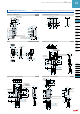
Selection
Guide
PM-24
PM-64
PM-44/54
U-shaped
Convergent
Reflective
PM2
PM2
437
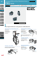
Convergent Reective Micro Photoelectric Sensor PM2 SERIES
Convergent
Reective
Color code of cable type
and connector attached cable
Brown
Black
Blue
Output
+V
0 V
Load
+
–
5 to 24 V DC
± 10 %
Type
Connector type Cable type
Top sensing Front sensing
L type (Top sensing)
Top sensing Front sensing
L type (Top sensing)
Model No.
Light-ON PM2-LH10 PM2-LF10 PM2-LL10 PM2-LH10-C1 PM2-LF10-C1 PM2-LL10-C1
Item
Dark-ON PM2-LH10B PM2-LF10B PM2-LL10B PM2-LH10B-C1 PM2-LF10B-C1 PM2-LL10B-C1
Sensing range
2.5 to 8 mm 0.098 to 0.315 in (Conv. point: 5 mm 0.197 in) with white non-glossy paper (15 × 15 mm 0.591 in × 0.591 in) (Note 2)
Min. sensing object ø0.05 mm ø0.002 in copper wire (Setting distance: 5 mm 0.197 in)
Hysteresis 20 % or less of operation distance with white non-glossy paper (15 × 15 mm 0.591 × 0.591 in)
Repeatability (perpendicular to sensing axis)
0.08 mm 0.003 in or less (Note 3)
Supply voltage 5 to 24 V DC ± 10 % Ripple P-P 5 % or less
Current consumption Average: 25 mA or less, Peak: 80 mA or less
Output
NPN open-collector transistor
Maximum sink current: 100 mA
Applied voltage: 30 V DC or less (between output and 0 V)
Residual voltage: 1 V or less (at 100 mA sink current)
0.4 V or less (at 16 mA sink current)
•
•
•
Utilization category DC-12 or DC-13
Overcurrent protection Incorporated
Response time 0.8 ms or less
Operation indicator Red LED (lights up when the output is ON)
Environmental resistance
Pollution degree 3 (Industrial environment)
Ambient temperature –10 to +55 °C +14 to +131 °F (No dew condensation or icing allowed), Storage: –25 to +80 °C –13 to +176 °F
Ambient humidity 45 to 85 % RH, Storage: 45 to 85 % RH
Ambient illuminance Incandescent light: 3,500 ℓx at the light-receiving face
EMC EN 60947-5
Vibration resistance 10 to 55 Hz frequency, 1.5 mm 0.059 in amplitude in X, Y and Z directions for two hours each
Shock resistance 500 m/s
2
acceleration (50 G approx.) in X, Y and Z directions for three times each
Emitting element Infrared LED (Peak emission wavelength: 880 nm 0.035 mil, modulated)
Material Enclosure: Polycarbonate, Terminal part: HSM (Ag plated) Enclosure: Polycarbonate, Fixed cable part: PBT
Cable
–
0.2 mm
2
3-core cabtyre cable, 1 m 3.281 ft long (Note 4)
Cable length
Total length up to 2 m 6.562 ft is possible with 0.3 mm
2
, or more, cable.
If the cable is extended for 2 m 6.562 ft, or more, a capacitor
of 10 µF must be connected between +V and 0 V terminals.
–
Weight
Net weight: 4.5 g approx.
Gross weight: 85 g approx.
(10 piece package)
Net weight: 4 g approx.
Gross weight: 80 g approx.
(10 piece package)
Net weight: 25 g approx
Gross weight: 330 g approx
(10 piece package)
SPECIFICATIONS
Notes: 1) Where measurement conditions have not been specied precisely, the conditions used were an ambient temperature of +23 °C +73.4 °F.
2) The sensing range may extend up to 12.5 mm
0.492 in with white non-glossy paper due to product variation.
3) The repeatability is specied for white non-glossy paper (15 × 15 mm
0.591 × 0.591 in) at a setting distance of 5 mm 0.197 in.
4) Cable cannot be extended.
I/O CIRCUIT AND WIRING DIAGRAMS
I/O circuit diagram
Color code of cable type and connector attached cable
Users
‚
circuit Internal circuit
Sensor circuit
(Brown) +V
100 mA max.
Load
(Black) Output
(Blue) 0 V
+
–
5 to 24 V DC
± 10 %
Tr
ZD
Note: Make sure to connect terminals correctly as the sensor does not
incorporate a reverse polarity protection circuit.
Symbols ... Z
D
: Surge absorption zener diode
Tr: NPN output transistor
Wiring diagram