
Datasheet


FIBER
SENSORS
LASER
SENSORS
PHOTO-
ELECTRIC
SENSORS
MICRO
PHOTO-
ELECTRIC
SENSORS
AREA
SENSORS
SAFETY
COMPONENTS
PRESSURE
SENSORS
INDUCTIVE
PROXIMITY
SENSORS
PARTICULAR
USE
SENSORS
SENSOR
OPTIONS
WIRE-
SAVING
SYSTEMS
MEASURE-
MENT
SENSORS
STATIC
CONTROL
DEVICES
LASER
MARKERS
MICRO
PHOTO-
ELECTRIC
SENSORS
Selection
Guide
PM-24
PM-64
PM-44/54
U-shaped
Convergent
Reflective
PM2
PM2
439
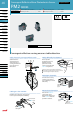
Convergent Reective Micro Photoelectric Sensor PM2 SERIES
Convergent
Reective
Connector type
Cautions in plugging or unplugging a connector
Procedures of plugging or unplugging a connector
1
Insert a connector straight into a
sensor until the connector lug is
locked by the sensor hook.
2
When unplugging, give as much
stress as a connector lug can
be relieved from a hook. Then
unplug it.
Hook
Lug
5 N or less
Caution: Be sure to hold a
connector when plugging
or unplugging it. Do
not hold a terminal or
a cable when plugging
or unplugging the
connector.Otherwise, it
will cause a poor contact.
CN 13
0V OUT +V
1.5 mm
0.059 in
Soldering
position
0V OUT+V
Soldering (Both connector CN-13 and sensor)
If soldering is done directly on the terminals, strictly
adhere to the conditions given below.
•
Soldering temperature
260 °C 500 °F or less
Soldering time 10 sec. or less
Soldering position Refer to the below gure
Sensor Connector
Wiring
The cable length must
be 2 m 6.562 ft, or
less, with 0.3 mm
2
,
or more, cable. If the
cable is extended for
more than 2 m 6.562 ft,
connect a capacitor of
10 µF approx. between
+V and 0 V terminals.
•
0V OUT
+
V
10 µF
Cable
5 to 24 V DC
± 10 %
+
–
Sensor
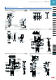
PM2-LH10 PM2-LH10B
10
0.394
5
0.197
3.3
0.130
7.2
0.283
Sensing surface
26
1.024
20
0.787
14
0.551
Operation
indicator (Red)
2-mounting oblong holes
3.2
0.126
6
0.236
25
0.984
1 0.039
8.4
0.331
4
0.157
3.2
0.126
15
0.591
17
0.669
15
0.591
Sensor
PM2-LF10 PM2-LF10B
26
1.024
20
0.787
14
0.551
7.2
0.283
3.2
0.126
6
0.236
25
0.984
13
0.512
15
0.591
1 0.039
8.4
0.331
4
0.157
4
0.157
10
0.394
Sensing surface
2-mounting oblong holes
Operation
indicator (Red)
3.3
0.130
15
0.591
3.2
0.126
5
0.197
DIMENSIONS (Unit: mm in)
The CAD data in the dimensions can be downloaded from the SUNX website: http://www.sunx.com
PRECAUTIONS FOR PROPER USE
Refer to p.986~ for general precautions.
Do not plug or unplug a connector more than
10 times.
Be sure not to give stress more than 5 N to a
terminal of both a connector and a sensor.
If you do not follow the above cautions, it will
cause a poor contact.
•
•