English Safety Information 1 CAUTION: • PLEASE FOLLOW THE LAWS AND REGULATIONS OF YOUR STATE, PROVINCE OR COUNTRY FOR INSTALLATION OF THE UNIT. • TO REDUCE THE RISK OF FIRE OR ELECTRIC SHOCK OR PRODUCT DAMAGE, DO NOT EXPOSE THIS APPLIANCE TO RAIN, SPLASHING, DRIPPING OR MOISTURE.
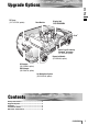
English Upgrade Options TV Tuner (CY-TUP153N, option) 2 Display Unit Rear Monitor CQ-VD6503N iPod® Hands-Free Kit featuring Bluetooth® technology (CY-BT100N, option) Expansion Module (CY-EM100N, option) CD Changer (CX-DP880N, option) DVD Changer (CX-DH801N, option) Car Navigation System (CN-DV2300N, option) Contents Safety Information................................................2 Upgrade Options ..................................................3 Contents..........................................
English Installation Guide 3 Preparation Caution ¡Please follow the laws and regulations of your province or country for installation of the unit. ¡When bending the mounting tab of the mounting collar with a screwdriver, be careful not to injure your hands and fingers. ¡We strongly recommend you to wear gloves for installation work to protect yourself from injuries. Dashboard Installation Installation Opening The unit can be installed in any dashboard having an opening as shown below.
No. Item ❏ Transportation Bracket Removal Diagram q Trim Plate Qty. 1 w Mounting Collar Be sure to remove the transportation brackets before use (installation). Use round head screws (5 mmø x 8 mm) for installation. (a page 7) Be careful not to lose these screws.
English Installation Guide 5 (continued) Mounting and removing the Display Unit ❏ Mounting Procedures (A) (When using Mounting Collar w) IMPORTANT When this unit is installed in dashboard, ensure that there is sufficient air flow around the unit to prevent damage from overheating. Do not block any ventilation holes on the unit.
(When not using Mounting Collar w) Use the brackets supplied with your car when mounting this unit. The bracket shape and mounting method vary with car manufacturers, car types and manufacturing year. Please consult your nearest dealer or installer. ❏ Removing Procedures English ❏ Mounting Procedures (B) 6 q Remove the trim plate q. q w w Lock release. q Insert the lock cancel plate e until you hear a click. Note: Use pliers to bend the fingers on the bracket vertically. w Pull the unit out.
(continued) English Installation Guide Connecting the Side Brake (Parking Brake) Connection Lead 7 ¡For safety, be sure to ask your nearest professional installer to do this connection. Caution Hand brake Foot brake Side brake (parking brake) switch The side brake (parking brake) switch position varies with car model. For details on the exact location of the side brake (parking brake) switch in your car, contact your dealer.
Caution ¡Check the connectors provided on your car (see precaution below) before connecting the system. ¡This unit is designed for use in a car having a 12 V negative ground battery system. ¡To prevent damage to the unit, be sure to follow the connection diagram. ¡Strip about 5 mm of the lead ends for connection (only non-ISO connector cords). ¡Do not insert the power connector into the unit until the wiring is completed.
English Electrical Connections (continued) ❏ Wiring Diagram 9 5 6 8 mmMA X CQ-VD6503N (Rear) FUSE 1 5 A >PBT< 1 2 3 J A M- S A a 4 Fuse (15 A) Refer fuse replacement to your nearest authorized Panasonic Service Centre. Do not try fuse replacement by yourself. (Black) (White) (R)(Red) (L)(White) (Yellow) (Black) (Red) q Subwoofer connector (mono) w Pre-Out To external amplifier. Connector (rear) e Pre-Out To external amplifier. Pre-Out Connector (centre) To external amplifier.
RGB Connector To the Panasonic Car Navigation System. Radio Antenna Connector (RADIO ANT IN) !1 ISO Antenna Adapter (If needed) System-up Connector To external devices equipped with system-up connector. i Power Connector To power connector of the unit. REVERSE SIDE BRAKE Speakers B8 : Rear Left – B7 : Rear Left + B6 : Front Left – B5 : Front Left + English Reverse Lead (Violet/white stripe) When connecting the rear view camera, use the reverse lead.
English Electrical Connections (continued) Connection with DVD Changer (CX-DH801N) Note: ¡Refer to the operating instructions for the connected devices, in addition.
English Connection with CD Changer (CX-DP880N) Note: ¡Refer to the operating instructions for the connected devices, in addition.
English Electrical Connections (continued) Connection with TV Tuner (CY-TUP153N) Note: ¡Refer to the operating instructions for the connected devices, in addition.
Note: ¡Refer to the operating instructions for the connected devices, in addition.
English Electrical Connections 15 (continued) Connection with Rear Monitor Note: ¡Refer to the operating instructions for the connected devices, in addition. ¡Please observe what shapes the connectors of the connecting devices are and where each of them is connected to in order to establish a proper connection. STAND BY (R) ON (G) COLOR LCD MONITOR Caution ¡For people sitting in the front seats, please enjoy only audio during driving.
English Connection with Rear View Camera Note: ¡Refer to the operating instructions for the connected devices, in addition.
English Electrical Connections 17 (continued) Connection with VCR or Camcorder Note: ¡Refer to the operating instructions for the connected devices, in addition. ¡Please observe what shapes the connectors of the connecting devices are and where each of them is connected to in order to establish a proper connection.
Note: ¡Refer to the operating instructions for the connected devices, in addition.