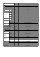
Order No. PHAAM0905053C2 Air Conditioner Indoor Unit Outdoor Unit CS-CE9JKE CU-CE9JKE CS-CE12JKE CU-CE12JKE TABLE OF CONTENTS 1 2 3 4 5 6 7 8 9 PAGE Safety Precautions----------------------------------------------- 3 Specifications ----------------------------------------------------- 5 Features ------------------------------------------------------------11 Location of Controls and Components ------------------12 4.1. Indoor Unit--------------------------------------------------12 4.2.
12.7. Indication Panel------------------------------------------- 33 13 Protection Control ---------------------------------------------- 34 13.1. Protection Control For All Operations--------------- 34 13.2. Protection Control For Cooling & Soft Dry Operation--------------------------------------------------- 36 13.3. Protection Control For Heating Operation --------- 37 14 Servicing Mode -------------------------------------------------- 38 14.1.
1 Safety Precautions • Read the following “SAFETY PRECAUTIONS” carefully before perform any servicing. • Electrical work must be installed or serviced by a licensed electrician. Be sure to use the correct rating of the power plug and main circuit for the model installed. • The caution items stated here must be followed because these important contents are related to safety. The meaning of each indication used is as below.
18. For R410A models, when connecting the piping, do not use any existing (R22) pipes and flare nuts. Using such same may cause abnormally high pressure in the refrigeration cycle (piping), and possibly result in explosion and injury. Use only R410A materials. Thickness of copper pipes used with R410A must be more than 0.8mm. Never use copper pipes thinner than 0.8mm. It is desirable that the amount of residual oil is less than 40 mg/10m. 19.
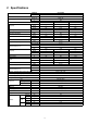
2 Specifications MODEL INDOOR CS-CE9JKE OUTDOOR CU-CE9JKE Performance Test Condition EUROVENT Phase, Hz Power Supply Capacity Running Current Cooling Input Power EER Indoor Noise (H / L) Outdoor Noise (H / L) 230 Min. Mid. Max. 3.00 kW 0.60 2.60 BTU/h — — — Kcal/h 520 2240 2580 A — 2.8 — 750 W 125 590 kWh — 295 — W/W 4.80 4.41 4.00 Kcal/hW 4.16 3.80 3.
MODEL INDOOR CS-CE9JKE OUTDOOR CU-CE9JKE Type Propeller Fan Outdoor Fan Material PP Motor Type DC Type (8-poles) Input Power W — Output Power W 40 rpm 800 Speed Hi Cool Heat Moisture Removal Lo 5.4 (190) m3/min (ft3/min) 6.4 (230) m3/min 8.0 (280) Cool/Fan Me Heat Hi Outdoor Airflow 790 1.6 (3.4) Cool/Fan m3/min (ft3/min) Heat Indoor Airflow rpm L/h (Pt/h) (ft3/min) 3 3 9.3 (330) 3 3 11.
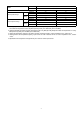
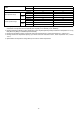
MODEL Cooling Indoor Operation Range Heating Cooling Outdoor Operation Range Heating INDOOR CS-CE9JKE OUTDOOR CU-CE9JKE Maximum Dry Bulb Wet Bulb 32 23 Minimum 16 11 Maximum 30 — Minimum 16 — Maximum 43 26 Minimum 16 11 Maximum 24 18 Minimum -15 -6 1. Cooling capacities are based on indoor temperature of 27°C Dry Bulb (80.6°F Dry Bulb), 19.0°C Wet Bulb (66.2°F Wet Bulb) and outdoor air temperature of 35°C Dry Bulb (95°F Dry Bulb), 24°C Wet Bulb (75.2°F Wet Bulb) 2.
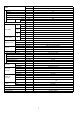
MODEL INDOOR CS-CE12JKE OUTDOOR CU-CE12JKE Performance Test Condition EUROVENT Power Supply Phase, Hz Single, 50 V 230 Cooling Capacity Mid. Max. 0.60 3.50 4.00 BTU/h — — — Kcal/h 520 3010 3440 Running Current A — 4.4 — Input Power W 125 915 1.18k Annual Consumption EER kWh — 458 — W/W 4.80 3.83 3.39 Kcal/hW 4.16 3.29 2.
MODEL INDOOR CS-CE12JKE OUTDOOR CU-CE12JKE Type Propeller Fan Outdoor Fan Material PP Motor Type DC Type (8-poles) Input Power W — Output Power W 40 rpm 840 Speed Hi Cool Heat Moisture Removal Lo 6.3 (220) m3/min (ft3/min) 9.4 (332) m3/min 8.5 (300) Cool/Fan Me Heat Hi Outdoor Airflow 820 2.0 (4.2) Cool/Fan m3/min (ft3/min) Heat Indoor Airflow rpm L/h (Pt/h) (ft3/min) 3 3 11.0 (389) 3 3 12.
MODEL Cooling Indoor Operation Range Heating Cooling Outdoor Operation Range Heating INDOOR CS-CE12JKE OUTDOOR CU-CE12JKE Dry Bulb Wet Bulb Maximum 32 23 11 Minimum 16 Maximum 30 — Minimum 16 — Maximum 43 26 Minimum 16 11 Maximum 24 18 Minimum -15 -6 1. Cooling capacities are based on indoor temperature of 27°C Dry Bulb (80.6°F Dry Bulb), 19.0°C Wet Bulb (66.2°F Wet Bulb) and outdoor air temperature of 35°C Dry Bulb (95°F Dry Bulb), 24°C Wet Bulb (75.2°F Wet Bulb) 2.
3 Features • Inverter Technology - Wider output power range - Energy saving - More precise temperature control • Environment Protection - Non-ozone depletion substances refrigerant (R410A) • Long Installation Piping - Long piping up to 15 meters during single split connection only • Easy to use remote control • Quality Improvement - Random auto restart after power failure for safety restart operation - Gas leakage protection - Prevent compressor reverse cycle - Inner protector to protect Compressor - Noise
4 Location of Controls and Components 4.1. Indoor Unit 4.2. Outdoor Unit 4.3.
5 Dimensions 5.1.
5.2.
6 Refrigeration Cycle Diagram 15
7 Block Diagram 16
8 Wiring Connection Diagram 8.1.
8.2.
9 Electronic Circuit Diagram 9.1.
9.2.
10 Printed Circuit Board 10.1. Indoor Unit 10.1.1.
10.1.2. Power Printed Circuit Board 10.1.3.
10.2.
11 Installation Instruction 11.1. Select the Best Location 11.1.1. 11.1.3. Indoor Unit • Do not install the unit in excessive oil fume area such as kitchen, workshop and etc. • There should not be any heat source or steam near the unit. • There should not be any obstacles blocking the air circulation. • A place where air circulation in the room is good. • A place where drainage can be easily done. • A place where noise prevention is taken into consideration. • Do not install the unit near the door way.
11.2. Indoor Unit 11.2.1. How to Fix Installation Plate 11.2.2. The mounting wall is strong and solid enough to prevent it from the vibration. To Drill a Hole in the Wall and Install a Sleeve of Piping 1. Insert the piping sleeve to the hole. 2. Fix the bushing to the sleeve. 3. Cut the sleeve until it extrudes about 15 mm from the wall. When the wall is hollow, please be sure to use the sleeve for tube ass’y to prevent dangers caused by mice biting the connecting cable. 4.
1. For the right rear piping 2. For the right and right bottom piping 3. For the embedded piping (This can be used for left rear piping and bottom piping also.
11.2.4. Connect the Cable to the Indoor Unit 1. The inside and outside connecting cable can be connected without removing the front grille. 2. Connecting cable between indoor unit and outdoor unit shall be approved polychloroprene sheathed 4 x 1.5 mm2 flexible cord, type designation 245 IEC 57 or heavier cord. • Secure the connecting cable onto the control board with the holder (clamper). This equipment must be properly earthed. • Ensure the colour of wires of outdoor unit and the terminal Nos.
11.3. Outdoor Unit 11.3.1. Install the Outdoor Unit • After selecting the best location, start installation according to Indoor/Outdoor Unit Installation Diagram. 1. Fix the unit on concrete or rigid frame firmly and horizontally by bolt nut (ø10 mm). 2. When installing at roof, please consider strong wind and earthquake. Please fasten the installation stand firmly with bolt or nails. Model CE9*** CE12*** 11.3.2. A B C D 570 mm 105 mm 18.
4. Close the Low side valve of the charging set and turn off the vacuum pump. Make sure that the needle in the gauge does not move after approximately five minutes. Note: BE SURE TO TAKE THIS PROCEDURE IN ORDER TO AVOID REFRIGERANT GAS LEAKAGE. 5. Disconnect the charging hose from the vacuum pump and from the service port of the 3-way valve. 6. Tighten the service port caps of the 3-way valve at a torque of 18 N•m with a torque wrench. 7. Remove the valve caps of both of the 2-way valve and 3-way valve.
12 Operation and Control 12.1. Basic Function Inverter control, which equipped with a microcomputer in determining the most suitable operating mode as time passes, automatically adjusts output power for maximum comfort always. In order to achieve the suitable operating mode, the microcomputer maintains the set temperature by measuring the temperature of the environment and performing temperature shifting.
12.1.5. Automatic Operation • This mode can be set using remote control and the operation is decided by remote control setting temperature, remote control operation mode, indoor intake air temperature and outdoor air temperature. • During operation mode judgment, indoor fan motor (with speed of Lo-) and outdoor fan motor are running for 30 seconds to detect the indoor intake and outdoor air temperature. The operation mode is decided based on below chart.
[Heating] • According to indoor pipe temperature, automatic heating fan speed is determined as follows. B. Feedback control • Immediately after the fan motor started, feedback control is performed once every second. • During fan motor on, if fan motor feedback 2550 rpm or < 50 rpm continue for 10 seconds, then fan motor error counter increase, fan motor is then stop and restart. If the fan motor counter becomes 7 times, then H19 - fan motor error is detected. Operation stops and cannot on back. 12.3.
12.4.2. Horizontal Airflow • The horizontal airflow direction louvers can be adjusted manually by hand. 12.5. Timer Control 12.5.1. ON Timer Control • ON timer can be set using remote control, the unit with timer set will start operate earlier than the setting time. This is to provide a comfortable environment when reaching the set ON time.
13 Protection Control 13.1. Protection Control For All Operations 13.1.1. Restart Control (Time Delay Safety Control) • The Compressor will not turn on within 3 minutes from the moment operation stops, although the unit is turned on again by pressing OFF/ON button at remote control within this period. • This control is not applicable if the power supply is cut off and on again. • This phenomenon is to balance the pressure inside the refrigerant cycle. 13.1.2.
13.1.5. Compressor Overheating Prevention Control • Instructed frequency for compressor operation will be regulated by compressor discharge temperature. The changes of frequency are as below. • If compressor discharge temperature exceeds 112°C, compressor will be stopped, occurs 4 times per 20 minutes, timer LED will be blinking. (“F97” is indicated.) 13.1.6. Low Pressure Prevention Control (Gas Leakage Detection) a.
13.2. Protection Control For Cooling & Soft Dry Operation 13.2.1. Outdoor Air Temperature Control • The compressor operating frequency is regulated in accordance to the outdoor air temperature as shown in the diagram below. • This control will begin 1 minute after the compressor starts. • Compressor frequency will adjust base on outdoor air temperature. 13.2.2.
13.2.6. Dew Prevention Control 2 • To prevent dew formation at indoor unit discharge area. • This control starts if all conditions continue for 20 minutes: - Operated with Cooling or Soft Dry Mode. - Indoor intake temperature is between 25°C and 29°C. - Outdoor air temperature is less than 30°C. • This control stopped if: - When receive air swing change signal from Remote Control. • The horizontal louver will be fixed at 26° (regardless of Auto or Manual Airflow Direction Setting). 13.3.
14 Servicing Mode 14.1. Auto OFF/ON Button 1. AUTO OPERATION MODE The Auto operation will be activated immediately once the Auto OFF/ON button is pressed. This operation can be used to operate air conditioner with limited function if remote control is misplaced or malfunction. 2. TEST RUN OPERATION (FOR PUMP DOWN/SERVICING PURPOSE) The Test Run operation will be activated if the Auto OFF/ON button is pressed continuously for more than 5 seconds.
4. REMOTE CONTROL RECEIVING SOUND OFF/ON MODE The Remote Control Receiving Sound OFF/ON Mode will be activated if the Auto OFF/ON button is pressed continuously for more than 16 seconds (4 “beep” sounds will occur at 16th seconds to identify the Remote Control Receiving Sound Off/On Mode is in standby condition) and press “AC Reset” button at remote control. Press “Auto OFF/ON button” to toggle remote control receiving sound. - Short “beep”: Turn OFF remote control receiving sound.
15 Troubleshooting Guide 15.1. Refrigeration Cycle System In order to diagnose malfunctions, make sure that there are no electrical problems before inspecting the refrigeration cycle. Such problems include insufficient insulation, problem with the power source, malfunction of a compressor and a fan. The normal outlet air temperature and pressure of the refrigeration cycle depends on various conditions, the standard values for them are shown in the table on the right.
15.1.1.
15.2. Breakdown Self Diagnosis Function 15.2.1. Self Diagnosis Function (Three Digits Alphanumeric Code) 7. The breakdown diagnosis mode will be canceled unless pressing the CHECK button continuously for 5 seconds or operating the unit for 30 seconds. 8. The same diagnosis can be repeated by turning power on again. • Once abnormality has occurred during operation, the unit will stop its operation, and Timer LED blinks.
15.3.
Diagnosis display Abnormality / Protection control Abnormality Judgement Protection operation F97 Compressor overheating protection 3 times happen within 30 minutes — Compressor overheat • Insufficient refrigerant F98 Total running current protection 3 times happen within 20 minutes — Total current protection • Check refrigeration system • Power source or compressor lock F99 Outdoor direct current (DC) peak detection Continuous happen for 7 times — Power transistor module current protect
15.4. Self-diagnosis Method 15.4.1. H11 (Indoor/Outdoor Abnormal Communication) Malfunction Decision Conditions During startup and operation of cooling and heating, the data received from outdoor unit in indoor unit signal transmission is checked whether it is normal. Malfunction Caused • Faulty indoor unit PCB. • Faulty outdoor unit PCB. • Indoor unit-outdoor unit signal transmission error due to wrong wiring.
15.4.2. H14 (Indoor Intake Air Temperature Sensor Abnormality) Malfunction Decision Conditions During startup and operation of cooling and heating, the temperatures detected by the indoor intake air temperature sensor are used to determine sensor errors. Malfunction Caused • Faulty connector connection. • Faulty sensor. • Faulty PCB.
15.4.3. H15 (Compressor Temperature Sensor Abnormality) Malfunction Decision Conditions During startup and operation of cooling and heating, the temperatures detected by the outdoor compressor temperature sensor are used to determine sensor errors. Malfunction Caused • Faulty connector connection. • Faulty sensor. • Faulty PCB.
15.4.4. H16 (Outdoor Current Transformer Open Circuit) Malfunction Decision Conditions A current transformer (CT) is detected by checking the compressor running frequency ( rated frequency) and CT detected input current (less than 0.65A) for continuously 20 seconds.
15.4.5. H19 (Indoor Fan Motor - DC Motor Mechanism Locked) Malfunction Decision Conditions The rotation speed detected by the Hall IC during fan motor operation is used to determine abnormal fan motor (feedback of rotation > 2550rpm or < 50rpm) Malfunction Caused • Operation stops due to short circuit inside the fan motor winding. • Operation stops due to breaking of wire inside the fan motor. • Operation stops due to breaking of fan motor lead wires. • Operation stops due to Hall IC malfunction.
15.4.6. H23 (Indoor Pipe Temperature Sensor Abnormality) Malfunction Decision Conditions During startup and operation of cooling and heating, the temperatures detected by the indoor heat exchanger temperature sensor are used to determine sensor errors. Malfunction Caused • Faulty connector connection. • Faulty sensor. • Faulty PCB.
15.4.7. H27 (Outdoor Air Temperature Sensor Abnormality) Malfunction Decision Conditions During startup and operation of cooling and heating, the temperatures detected by the outdoor air temperature sensor are used to determine sensor errors. Malfunction Caused • Faulty connector connection. • Faulty sensor. • Faulty PCB.
15.4.8. H28 (Outdoor Pipe Temperature Sensor Abnormality) Malfunction Decision Conditions During startup and operation of cooling and heating, the temperatures detected by the outdoor pipe temperature sensor are used to determine sensor errors. Malfunction Caused • Faulty connector connection. • Faulty sensor. • Faulty PCB.
15.4.9. H30 (Compressor Discharge Temperature Sensor Abnormality) Malfunction Decision Conditions During startup and operation of cooling and heating, the temperatures detected by the outdoor discharge pipe temperature sensor are used to determine sensor errors. Malfunction Caused • Faulty connector connection. • Faulty sensor. • Faulty PCB.
15.4.10. H33 (Unspecified Voltage between Indoor and Outdoor) Malfunction Decision Conditions The supply power is detected for its requirement by the indoor/outdoor transmission. Malfunction Caused • Wrong models interconnected. • Wrong indoor unit and outdoor unit PCBs used. • Indoor unit or outdoor unit PCB defective.
15.4.11. H97 (Outdoor Fan Motor - DC Motor Mechanism Locked) Malfunction Decision Conditions The rotation speed detected by the Hall IC during fan motor operation is used to determine abnormal fan motor. Malfunction Caused • Operation stops due to short circuit inside the fan motor winding. • Operation stops due to breaking of wire inside the fan motor. • Operation stops due to breaking of fan motor lead wires. • Operation stops due to Hall IC malfunction. • Operation error due to faulty outdoor unit PCB.
15.4.12. H98 (Indoor High Pressure Protection) Error Code will not display (no Timer LED blinking) but store in EEPROM Malfunction Decision Conditions During heating operation, the temperature detected by the indoor pipe temperature sensor is above 60°C.
15.4.13.
15.4.14.
15.4.15. F90 (Power Factor Correction Protection) Malfunction Decision Conditions During startup and operation of cooling and heating, when Power Factor Correction (PFC) protection circuitry at the outdoor unit main PCB senses abnormal high DC voltage level. Malfunction Caused • DC voltage peak due to power supply surge. • DC voltage peak due to compressor windings not uniform. • Faulty outdoor PCB.
15.4.16. F91 (Refrigeration Cycle Abnormality) Malfunction Decision Conditions • During cooling, compressor frequency = Fcmax. • During heating, compressor frequency > Fhrated. • During cooling and heating operation, running current: 0.65A < I < 1.65A.
15.4.17. F93 (Compressor Rotation Failure) Malfunction Decision Conditions A compressor rotation failure is detected by checking the compressor running condition through the position detection circuit.
15.4.18. F95 (Cooling High Pressure Abnormality) Malfunction Decision Conditions During operation of cooling, when outdoor unit heat exchanger high temperature data (61°C) is detected by the outdoor pipe temperature sensor. Malfunction Caused • Outdoor pipe temperature rise due to short circuit of hot discharge air flow. • Outdoor pipe temperature rise due to defective of outdoor fan motor. • Outdoor pipe temperature rise due to defective outdoor pipe temperature sensor.
15.4.19. F96 (IPM Overheating) Malfunction Decision Conditions During operating of cooling and heating, when IPM temperature data (100°C) is detected by the IPM temperature sensor. Multi Models Only • Compressor Overheating: During operation of cooling and heating, when the compressor OL is activated. • Heat Sink Overheating: During operation of cooling and heating, when heat sink temperature data (90°C) is detected by the heat sink temperature sensor.
15.4.20. F97 (Compressor Overheating) Malfunction Decision Conditions During operation of cooling and heating, when compressor tank temperature data (112°C) is detected by the compressor tank temperature sensor. Malfunction Caused • Refrigerant shortage (refrigerant leakage). • 2/3 way valve closed. • Detection error due to faulty compressor tank temperature sensor.
15.4.21. F98 (Input Over Current Detection) Malfunction Decision Conditions During operation of cooling and heating, when an input over-current (14.98A) is detected by checking the input current value being detected by current transformer (CT) with the compressor running. Malfunction Caused • Over-current due to compressor failure. • Over-current due to defective outdoor unit PCB. • Over-current due to defective inverter main circuit electrolytic capacitor. • Over-current due to excessive refrigerant.
15.4.22. F99 (Output Over Current Detection) Malfunction Decision Conditions During operation of cooling and heating, when an output over-current (20.2A) is detected by checking the current that flows in the inverter DC peak sensing circuitry. Malfunction Caused • DC peak due to compressor failure. • DC peak due to defective power transistor(s). • DC peak due to defective outdoor unit PCB. Troubleshooting 20.
16 Disassembly and Assembly Instructions High voltages are generated in the electrical parts area by the capacitor. Ensure that the capacitor has discharged sufficiently before proceeding with repair work. Failure to heed this caution may result in electric shocks. 16.1. Indoor Electronic Controllers, Cross Flow Fan and Indoor Fan Motor Removal Procedures 16.1.1. To remove front grille 16.1.2.
16.1.3.
16.1.4. To remove control board 16.1.5.
16.2. Outdoor Electronic Controller Removal Procedure Caution! When handling electronic controller, be careful of electrostatic discharge. 5. Remove the Control Board as follows: 1. Remove the 3 screws of the Top Panel. Fig. 1 Fig. 4 2. Remove the 6 screws of the Front Panel. Fig. 2 3. Remove the screw of the Terminal Board Cover. 4. Remove the Top Cover of the Control Board by 4 hooks. Fig. 5 Fig. 6 Fig.
17 Technical Data 17.1. Operation Characteristics 17.1.1.
17.1.2.
17.2. Sensible Capacity Chart O CU-CE9JKE 230V Outdoor Temp. (°C) 30 35 40 46 Indoor wet bulb temp. TC SHC IP TC SHC IP TC SHC IP TC SHC IP 17.0°C 2.58 1.96 0.54 2.41 1.88 0.58 2.24 1.80 0.62 2.04 1.71 0.67 19.0°C 2.60 0.59 19.5°C 2.83 2.05 0.55 2.65 1.97 0.59 2.46 1.89 0.63 2.24 1.80 0.68 22.0°C 3.09 2.12 0.56 2.88 2.04 0.60 2.68 1.97 0.64 2.44 1.88 0.70 O CU-CE12JKE 230V Outdoor Temp. (°C) 30 35 40 46 Indoor wet bulb temp.
18 Exploded View and Replacement Parts List 18.1. Indoor Unit Note The above exploded view is for the purpose of parts disassembly and replacement. The non-numbered parts are not kept as standard service parts.
REF. NO. QTY. CS-CE9JKE CS-CE12JKE 1 CHASSY COMPLETE PART NAME & DESCRIPTION 1 CWD50C1599 ← 2 FAN MOTOR 1 ARW6101CB ← 3 CROSS FLOW FAN COMPLETE 1 CWH02C1076 ← 4 BEARING ASS’Y 1 CWH64K007 ← 5 SCREW - CROSS FLOW FAN 1 CWH551146 ← 6 EVAPORATOR CO.
18.2. Outdoor Unit Note The above exploded view is for the purpose of parts disassembly and replacement. The non-numbered parts are not kept as standard service parts.
REF. NO. QTY.