Order No: MAC0704001A2 e lifi p Sim INDOOR UNIT CS-E7GKEW CS-E9GKEW CS-E12GKEW CS-E15GKEW CS-E18GKEW d Panasoni c CS-E7GKDW CS-E9GKDW CS-E12GKDW CS-E15GKDW CS-E18GKDW OUTDOOR UNIT CU-2E15GBE AU HEA TO CO T O DR L Y FA SPEN ED Panasonic e -Io MO DE n OF PA FAN TE MP QU IET AIR TIM SWIN GP ON ER OW ERFU 1 OF F SET AIR SW ING F/O N TR OL SPEE D L SE T 2 3 CH EC KC CA NC AC EL LO Pa RC na CK so ni RESET IN VER c TE R AU HEA TO CO T O DR L Y e -Io MO DE QU IET TE TIM ON ER F FA SPE
4.1 4.2 4.3 5. Indoor Unit ....................................................8 Outdoor Unit .................................................9 Remote Control ............................................9 13. 13.1 13.2 13.3 Dimensions...................................................10 5.1 5.2 Indoor Unit & Remote Control ....................10 Outdoor Unit ...............................................12 6. Refrigeration Cycle Diagram.......................13 7. Block Diagram ...................
1. Safety Precautions • • • • Read the following “SAFETY PRECAUTIONS” carefully before perform any servicing. Electrical work must be installed or serviced by a licensed electrician. Be sure to use the correct rating of the power plug and main circuit for the model installed. The caution items stated here must be followed because these important contents are related to safety. The meaning of each indication used is as below.
CAUTION 1. The equipment must be earthed. It may cause electrical shock if grounding is not perfect. 2. Do not install the unit at place where leakage of flammable gas may occur. In case gas leaks and accumulates at surrounding of the unit, it may cause fire. 3. Carry out drainage piping as mentioned in installation instructions. If drainage is not perfect, water may enter the room and damage the furniture. 4.
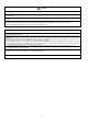
2. Specifications 2.
2.
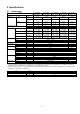
3. Features • Product o A single outdoor unit enables air conditioning of up to two separate rooms for CU-2E15GBE, CU-2E18CBPG. o A single outdoor unit enables air conditioning of up to three separate rooms for CU-3E18EBE, CU-3E23CBPG. o A single outdoor unit enables air conditioning of up to four separate rooms for CU-4E27CBPG 2.2 kW Wall Duct Ceiling Floor CU-4E27CBPG B C D ● ● ● ● ● ● ● ● ● ● ● ● ● ● ● ● ● 4.0 kW CS-ME15DD3EG _ _ _ _ ● ● ● ● ● ● ● ● ● ● 5.
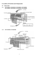
4. Location of Controls and Components 4.1 Indoor Unit 4.1.1 CS-E7GKEW, CS-E9GKEW, CS-E12GKEW, CS-E15GKEW CS-E7GKDW, CS-E9GKDW, CS-E12GKDW, CS-E15GKDW 4.1.
4.2 4.2.1 4.3 Outdoor Unit CU-2E15GBE Remote Control 4.3.1 CS-E7GKEW, CS-E9GKEW, CS-E12GKEW, CS-E15GKEW CS-E7GKDW, CS-E9GKDW, CS-E12GKDW, CS-E15GKDW 4.3.
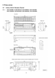
5. Dimensions 5.1 5.1.
5.1.
5.2 5.2.
6. Refrigeration Cycle Diagram OUTDOOR INDOOR A Expansion valve A 3-way valve Capillary tube Capillary tube Silencer Expansion valve B Silencer Heat Exchanger (Evaporator) 3-way valve 4-way Valve 3-way valve INDOOR B Dryer Compressor = sensor Type of pipe CZ-3F Type Liquid side pipe Ø 6.35 mm (1/4“) Gas side pipe Ø 9.
N L FUSE 5A RY-AC CT PTC3 PTC2 RY-PWR RY-C REACTOR HOT RY-HOT TO INDOOR UN TBI 1 2 3 TO INDOOR UN TAI 1 2 3 AC230V 50Hz FUSE 20A OUTDOOR UN TI SC FUSE 3.15A FM COMP 7.
PC301 PC302 15 PINK (P) RED(R) WHITE (W) YELLOW/GREEN (Y/G) YELLOW (Y) R327 Remark: BLACK (BL) BLUE (B) BROWN (BR) GREEN (G) GRAY (GR) ORANGE (O) R308 1 CN-FM R313 FAN MOTOR ZD301 ZD302 R R329 FM 7 6 5 4 PC307 D304 R321 C309 LF301 C315 C314 ZNR301 C313 DB301 10 1 1 1 GAS SENSOR G GND G 5 1 STEPPING MOTOR SENSOR 1 COMPLETE 13 CN-DISP WIRELESS REMOTE CONTROL 11 RECEIVER SENSOR 1 (AIR TEMP.
3 2 (N) PC301 PC302 16 PINK (P) RED(R) WHITE (W) YELLOW/GREEN (Y/G) YELLOW (Y) R327 Remark: BLACK (BL) BLUE (B) BROWN (BR) GREEN (G) GRAY (GR) ORANGE (O) R308 1 CN-FM R313 FAN MOTOR ZD301 ZD302 R R329 FM 7 6 5 4 PC307 D304 R321 C309 LF301 C315 C314 ZNR301 C313 DB301 12 1 1 1 G GND G 5 1 STEPPING MOTOR 5 1 STEPPING MOTOR SENSOR 1 COMPLETE 13 WIRELESS REMOTE CONTROL RECEIVER SENSOR 1 (AIR TEMP.
N TERMINAL FUSE T 5.0A L 250 V WH 1 BL BL BL FUSE 20.0A WH WH WH WH BR BL 4 3 2 1 4 3 2 1 WH WH WH WH CONNECTOR (BLACK) BL BL 4 3 CN - DC 2 (WHITE) 1 FG1 (GREEN) AC1 (BLACK) AC2 (BLACK) G Y/G TERMINAL 17 REACTOR GR CWHB090001 0.642 Ω 0.636 Ω 0.652 Ω CONNECTION R-B R-Y B-Y CONNECTOR (YELLOW) REMARKS B: BLUE BL: BLACK BR: BROWN G: GREEN R: RED WH: WHITE Y: YELLOW GR: GRAY OR: ORANGE FM B B V W Y THE PARENTHESIZED LETTERS IS INDICATED ON TERMINAL COVER. COMPRESSER R U COMP.
9. Electronic Circuit Diagram 9.1 9.1.
9.1.
9.2 Outdoor Unit CU-2E15GBE Outdoor WH R COMPRESSER FAN MOTOR B G 4 3 2 1 CN - DC (WHITE) AC1 (BLACK) AC2 (BLACK) FM REACTOR GR GR G R GRY1 (GRAY) FG1 (GREEN) 4 3 2 1 4 3 2 1 WH WH WH WH CN - DC (WHITE) 4 3 2 1 CONNECTOR (BLACK) BL BL AC1 (BLACK) AC2 (BLACK) WH WH WH WH COIL 20 COIL COMP. (4-WAYVALVE) W V U COIL COIL CN-FM1 4 5 6 7 (WHITE) HOT1 (BLACK) 1 BL CONNECTOR (YELLOW) FM1 (RED) PTC3 L FUSE 20.0A Y/G TERMINAL PTC2 RY - PWR P BL BL R P L RY - AC 12V FUSE T 5.
10. Printed Circuit Board 10.1 Indoor Unit 10.1.
10.1.2 Power Printed Circuit Board Applicable for the models below: CS-E7GKEW, CS-E9GKEW, CS-E12GKEW, CS-E15GKEW, CS-E18GKEW CS-E7GKDW, CS-E9GKDW, CS-E12GKDW, CS-E15GKDW, CS-E18GKDW 10.1.
10.1.4 Patrol Sensor Printed Circuit Board Applicable for the models below: CS-E7GKEW, CS-E9GKEW, CS-E12GKEW, CS-E15GKEW CS-E7GKDW, CS-E9GKDW, CS-E12GKDW, CS-E15GKDW 10.1.
10.
11. Installation Information 11.1 Check Points Indoor/outdoor unit connection cables (Not included in the unit) Outdoor unit power supply: Single-phase 230V, 50Hz Panasoni c Unit B 1.5mm2 flexible cord x 4 core (poluchloroprene sheathed) Panasoni c 20A switch (circuit breaker) (Not included in the unit) (Not included in the unit) Unit A Allowable elevation: 10m max. The allowable elevation between each of the indoor units and between the indoor and outdoor units. 1.
11.3 Piping Length Piping size Gas Common Length (m) Liquid Min. Total Length (m) Max. Total Length (m) Max. Elevation (m) Additional gas charge amount (g/m) 20 x 2 3/8” 1/4" 20 6 (3m / indoor unit) 30 x 1 10 Note: 1. It is possible to extend the piping length of one unit up to 20 meters. However, the total piping length must not exceed 30 meters. 2. If the piping length exceeds 20 meters, refrigerant of 20g per meter must be added.
12. Installation Instruction 12.1 Select the Best Location 12.1.1 • • • • • • • • There should not be any heat source or steam near the unit. There should not be any obstacles blocking the air circulation. A place where air circulation in the room is good. A place where drainage can be easily done. A place where noise prevention is taken into consideration. Do not install the unit near the door way. Ensure the spaces indicated by arrows from the wall, ceiling, fence or other obstacles.
12.2 Indoor Unit 12.2.1 How to Fix Installation Plate The mounting wall is strong and solid enough to prevent if from the vibration. The centre of installation plate should be at more than 450 mm at right and left of the wall. The distance from installation plate edge to ceiling should more than 67mm. From installation plate left edge to unit’s left side is 74mm. From installation plate right edge to unit’s right side is 94mm.
12.2.3 12.2.3.1 Indoor Unit Installation For the right rear piping Pull out the Indoor Piping Install the Indoor Unit Secure the Indoor Unit Insert the connecting cable 12.2.3.
12.2.3.3 For the embedded piping Replace the drain hose Bend the embedded piping • Use a spring bender or equivalent to bend the piping so that the piping is not crushed. Install the Indoor Unit Cut and flare the embedded piping • • When determining the dimensions of the piping, slide the unit all the way to the left on the installation plate. Refer to the section “Cutting and flaring the piping”.
12.2.4 Connect the Cable to the Indoor Unit 1. The inside and outside connecting cable can be connected without removing the front grille. 2. Connecting cable between indoor unit and outdoor unit shall be approved polychloroprene sheathed 3 (C9GK, C12GK) x 1.5mm2 flexible cord, type designation 245 IEC 57 or heavier cord. o Ensure the color of wires of outdoor unit and the terminal numbers are the same to the indoor’s respectively.
12.3.2.2 Connecting the piping to outdoor unit Decide piping length and then cut by using pipe cutter. Remove burrs from cut edge. Make flare after inserting the flare nut (locate at valve) onto the copper pipe. Align center of piping to valves and then tighten with torque wrench to the specified torque as stated in the table. 12.3.2.3 Cutting and flaring the piping 1. Please cut using pipe cutter and then remove the burrs. 2. Remove the burrs by using reamer.
CAUTION • If gauge needle does not move from 0cmHg (0MPa) to -76cmHg (-0.1MPa), in step 3 above take the following measure: • If the leak stops when the piping connections are tightened further, continue working from step 3. • If the leak does not stop when the connections are retightened, repair the location of leak. • Do not release refrigerant during piping work for installation and reinstallation. Take care of the liquid refrigerant, it may cause frostbite. 12.3.
13. Operation Control 13.1 Simultaneous Operation Control • • • • Operation modes which can be selected using the remote control unit: o Automatic, Cooling, Dry, Heating and e-ion operation mode.
13.2 Basic function Inverter control, which with a microcomputer in determining the most suitable operating mode as time passes, automatically adjusts output power for maximum comfort always. In order to achieve the suitable operating model, the microcomputer maintains the set temperature by measuring temperature of the environment and performing temperature shifting.
13.2.3 13.2.3.1 • • Soft dry operation Thermostat control Compressor is OFF when intake air temperature – Internal setting temperature <-1.5°C. Compressor is ON after waiting for 3 minutes, if the intake air temperature – Internal setting temperature > compressor OFF point. Intake air temperature – Internal setting temp. 2.5°C 0.5° Compressor ON -1.5° Compressor OFF 13.2.4 13.2.4.
13.2.5 • • Automatic operation This mode can be set using remote control and the operation is decided by remote control setting temperature, remote control operation mode, indoor intake temperature and outdoor air temperature. During operation mode judgment, indoor fan motor (with speed of Lo-) and outdoor fan motor are running for 30 seconds to detect the indoor intake and outdoor air temperature. The operation mode is decided based on below chart.
13.2.6 • Indoor fan motor operation Basic Rotation speed (rpm) o Manual fan speed [Cooling, Dry] Fan motor’s number of rotation is determined according to remote control setting. Remote control Tab (rpm) [Heating] O SHi O Me+ O Me O Me- O Lo Fan motor’s number of rotation is determined according to remote control setting.
13.2.7 • • Airflow direction There are two types of airflow, vertical airflow (directed by horizontal vane) and horizontal airflow (directed by vertical vanes). Control of airflow direction can be automatic (angles off direction is determined by operation mode, heat exchanger temperature and intake air temperature) and manual (angles of direction can be adjusted using remote control). 13.2.7.
13.2.7.2 • • Horizontal airflow For CS-E7, 9, 12, 15GKD/GKE, the horizontal airflow direction louvers can be adjusted manually by hand. For CS-E18GKD/GKE, automatic airflow direction can be set using remote control; the vane swings left and right within the angles as stated below. For heating mode operation, the angle of the vane depends on the indoor heat exchanger temperature as Figure 1 below.
13.2.9 Quiet operation (Heating) Purpose • To provide quiet heating operation compare to normal operation. Control condition • Quiet operation start condition 1. When “quiet” button at remote control is pressed. Quiet LED illuminates. • Quiet operation stop condition 1. When one of the following conditions is satisfied, quiet operation stops: o Powerful button is pressed. o Stop by OFF/ON switch. o Timer “off” activates. o Quiet button is pressed again. 2.
13.2.10 Powerful mode operation When the powerful mode is selected, the internal setting temperature will shift to achieve the setting temperature quickly. • Cooling operation Internal setting temperature 20min -2.0°C When powerful button is pressed • Soft dry operation Internal setting temperature 20min -1.0°C When powerful button is pressed • Heating Internal setting temperature 20min +3.
13.2.13 Indication panel LED Color Light ON Light OFF POWER Green Operation ON Operation OFF TIMER Orange Quiet setting ON Quiet setting OFF QUIET POWERFUL Orange Orange Quiet mode ON Powerful mode ON Quiet mode OFF Powerful mode OFF e-ion Blue e-ion ON e-ion OFF PATROL SENSOR Blue PATROL ON PATROL OFF Note: • If POWER LED is blinking, the possible operation of the unit are hot start, during deice operation, operation mode judgment, or ON timer sampling.
C. Control Content a) Gas Sensor Control • First 2 minutes from Patrol function activates is stabilization time, during stabilization time, no air dirtiness level is monitored. The Air Dirtiness level is set to level 2. • After that, gas sensor starts to record the resistance value at fixed interval. Higher resistance value indicates cleaner air. • The air dirtiness level is monitored by comparing the current resistance value with maximum resistance value from time to time to get the Air Dirtiness Value.
f) Indicator • When Patrol operation starts, Patrol Sensor indicator ON. • When e-ion operation starts based on dirtiness level, e-ion indicator ON. g) Remote Control Receiving Sound • Normal Operation Æ Patrol Mode • Patrol Mode Æ Stop • Patrol Mode Æ Normal Operation • Stop Æ Patrol : Beep : Long Beep : Beep : Beep h) Timer Control • When ON timer activates when unit stops, previous operation resumes without Patrol operation.
c) e-ion operation pause condition • When indoor fan stop (during deice, odor cut control, thermostat off, etc.). e-ion operation resume after indoor fan restarts. • When indoor intake temperature ≥ 40°C. e-ion operation resume after indoor intake temperature < 40°C continuously for 30 minutes. C. Control content a) Indoor fan control • During any operation mode combines with e-ion operation, fan speed follows respective operation mode.
13.2.16 Compressor Operation Frequency • The compressor operation frequency is determined by room temperature, capacity, and model type. a) When operation is started after the air conditioner has been stopped for more than one hour, the air conditioner operates at a high frequency which lowers the room temperature quickly for cooling (or raises it quickly for heating).
13.3 Protection Control for All Operations 13.3.1.1 • The compressor does not restart for 3 minutes after stop of compressor. 13.3.1.2 • • • Time delay safety control Total running current control When the air conditioner has been operated at the capacity designated by the indoor unit and the total running current exceeds setting I1, the operating frequency of the compressor is reduced.
13.3.1.5 Low Pressure Prevention Control (Gas Leakage Detection) • Control start conditions o For 5 minutes, the compressor continuously operates and outdoor total current is between 1.5A and 1.88A. o During Cooling and Soft Dry operations: Indoor heat exchanger temperature is above 20°C. o During heating operations: Indoor heat exchanger temperature is below 25°C. • Control contents o Compressor stops (and restart after 3 minutes).
13.3.2.2 • Outdoor air temperature control The compressor operating frequency is regulated in accordance to the outdoor air temperature as shown in the diagram below. This control will begin 1 minute after the compressor starts. 38°C Max:70Hz, Min:35Hz Free 30°C Free 22°C 37°C 28°C 20°C 17°C Max:59Hz, Min:16Hz Min:16Hz 15°C Outdoor air temperature 13.3.2.3 • 3 minutes after forced cooling operation was conducted for one room during the initial operation after power was turned on.
13.3.3.2 • Intake Air Temperature Control Compressor operating frequency changes in accordance to the outdoor air temperature. 18°C 11°C Max 70Hz Min 16Hz Max 99Hz Min 16Hz 17°C 10°C Free Outdoor air temperature • This control is not applicable during minimum frequency operation protection control, deice operation, pump down operation.
14. Servicing Mode 14.1 Auto OFF/ON Button Auto OFF/ON Button Pressed Auto OFF/ON Button Pressed 5 sec Auto Operation Auto OFF/ON Button Pressed 5 sec Test Run Operation (Forced Cooling Operation) Beep Stop Test Run Operation (Forced Heating Operation) Beep x 2 Stop 1. AUTO OPERATION MODE The Auto Operation will be activated immediately once the Auto OFF/ON button is pressed. This operation can be used to operate air conditioner with limited function if remote control is misplaced or malfunction. 2.
14.2 Select Remote Control Transmission Code • J_A • There are 4 types of remote control transmission code could be selected and stored in EEPROM of indoor unit. The indoor unit will only operate when received signal with same transmission code from remote control. This could prevent signal interference when there are 2 or more indoor units installed nearby together. To change remote control transmission code, short or open jumpers at the remote control printed circuit board.
15. Troubleshooting Guide 15.1 Refrigeration cycle system In order to diagnose malfunctions, ensure the air conditioner is free from electrical problems before inspecting the refrigeration cycle. Such problems include insufficient insulation, problem with the power source, malfunction of a compressor and a fan. The normal outlet air temperature and pressure of the refrigeration cycle depends on various conditions, the standard values for them are shown in the table to the right.
15.1.
15.2.1.2 To display memorized error (Protective operation) status 1. Turn power on. 2. Press the CHECK button on the remote controller continuously for 5 seconds. 3. “- -” will be displayed on the remote controller display. Note: Display only for “- -”. (No transmitting signal, no receiving sound and no Power LED blinking.) 4. Press the “TIMER” ▲ or ▼ button on the remote controller. The code “H00” (no abnormality) will be displayed and signal will be transmitted to the main unit. The power LED lights up.
15.2.1.
16. Disassembly and Assembly Instructions WARNING • • • When handling electronic controller, be careful of electrostatic discharge. Be sure to return the wiring to its original position. There are many high voltage components within the heat sink cover, so never touch the interior during operation. Wait at least two minutes after power has been turned off. 16.1 Indoor Unit (CS-E7GKEW, CS-E9GKEW, CS-E12GKEW, CS-E15GKEW CS-E7GKDW, CS-E9GKDW, CS-E12GKDW, CS-E15GKDW) 16.1.
• Press the Hold to right hand side, remove the Particular Piece and slide out the Main Electronic Controller. (Fig. 4) Fig. 4 • • • • • Release the CN-DATA1.(Fig. 5) Release the CN-CLN.(Fig. 5) Release the CN-FB.(Fig. 5) Release the CN-TH.(Fig. 5) Release the CN-STM1.(Fig. 5) Fig. 5 16.1.3 • • • • To Remove the Power Electronic Controller Release the screw for the Earth wire. (Fig. 6) Pull out 2 terminal wires (Black & Red) from the Terminal Board. (Fig.
16.1.4 • To Remove the Discharge Grille Pull out the Drain Hose (behind the Discharge Grille) from outlet to remove the Discharge Grille. (Fig. 8) Fig. 8 16.1.5 • • To Remove Control Board Release the 3 screws (Fig. 9) By pressing down the hook at left hand side of control board, you will be able to remove the Control Board. (Fig. 9) Fig. 9 16.1.6 To Remove the Cross Flow Fan and Indoor Fan Motor • Remove the screw at the Cross Flow Fan. (Fig.
• Lift up the Evaporator and remove the Cross Flow Fan from the unit by pulling it to the left and downward. Fan Motor can be removed after the removal of the Cross Flow Fan. (Fig. 12) Fig.
16.2 Indoor Unit (CS-E18GKEW, CS-E18GKDW) 16.2.1 • • To Remove the Front Grille Lift to open the vertical vent gently. Remove the 3 caps and 3 screws at the bottom of discharge vent. (Fig. 1) Remove the Front Grille by releasing the 3 hooks at the top of the Front Grille. Hold both sides of the Front Grille and remove it by pulling up and towards you gently. (Fig. 1) Fig. 1 • • Unhook the tabs at the Control Board to remove the Control Board Cover. (Fig 2) Release the Particular Piece. (Fig. 2) Fig.
• • • • • Release the CN-DATA1 connector (Fig. 5) Release the CN-TH connector (Fig. 5) Release the CN-CLN connector (Fig. 5) Release the CN-STM1 connector (Fig. 5) Release the CN-STM2 connector (Fig. 5) Fig. 5 16.2.3 • To Remove the Power Electronic Controller Release the hook that hold the Particular Piece and pull out the Power Electronic Controller. (Fig. 6) Fig. 6 • • Release the AC-303 connector. (Fig. 7) Release the CN-FM connector. (Fig. 7) Fig. 7 16.2.
16.2.6 To Remove the Cross Flow Fan and Indoor Fan Motor • Remove the screw at the Cross Flow Fan (Fig. 10) Reminder: To reinstall the Fan Motor, please adjust the connector location is positioned 90° with Fan Motor before fixing Control Board. (Fig. 10) Fig. 10 • • Remove the Bearing. (Fig. 11) Remove the screws at the left hand side of the Evaporator. (Fig 11) Fig. 11 • Push up the Evaporator and pull out the Cross Flow Fan from shaft. Then take out the Fan Motor. (Fig. 12) Fig.
16.3 Outdoor Unit 16.3.1 Removing the Cabinet Top Plate and Cabinet Front Plate 1. Remove the cabinet top plate (by removing the 4 screws). 2. Remove the 5 screws fixing the cabinet front plate, release 6 hooks and pull the cabinet front plate toward front side. 16.3.2 Removing the Control Board Cover 3. Remove the control board cover (remove 1 screw) 4. Remove the terminal cover (remove 2 screws) 5. Remove the terminal cover (top) and disconnect all the lead wires (3 fasten tab) inside. 16.3.
16.3.4 Removing the Propeller Fan and Fan Motor 1. Remove the cabinet top plate and cabinet front plate 2. Remove the propeller fan by removing the nut turning clockwise at its center. 3. Disconnect the connector of the fan motor from the control board. 4. Loosen the 4 screws at the fan motor mounting then remove the fan motor.
17. Technical Data 17.1 Operation Characteristics 17.1.1 Cooling Characteristic o Room temperature: o Operation condition: o Piping Length: 27°C (DBT), 19°C (WBT) High fan speed 7.5m Outlet Air (°C) 28kW 22kW 17.5 17.0 16.5 16.0 15.5 15.0 14.5 30 31 32 33 34 35 36 37 38 39 40 38 39 40 Outdoor Temperature (°C) 28kW 22kW Capacity(kW) 3.2 3.0 2.8 2.6 2.4 2.2 2.0 30 31 32 33 34 35 36 37 Outdoor Temperature (°C) 28kW Gas SidePiping Pressure (MPa) 22kW 1.14 1.10 1.06 1.02 0.
Heating Characteristic o Room temperature: o Operation condition: o Piping Length: 27°C (DBT), 19°C (WBT) High fan speed 7.5m 28kW 22kW Outlet Air (°C) 45 43 41 39 37 35 2 3 4 5 6 7 8 9 10 11 12 9 10 11 12 9 10 11 12 Outdoor Temperature (°C) 28kW 22kW Capacity (kW) 5.00 4.50 4.00 3.50 3.00 2.50 2 3 4 5 6 7 8 Outdoor Temperature (°C) 28kW Gas Side Piping Pressure (MPa) 22kW 3.2 3.0 2.8 2.6 2.4 2.
17.1.2 Two Indoor Unit Operation Cooling Characteristic o Room temperature: o Operation condition: o Outdoor temperature: 27°C (DBT), 19°C (WBT) High fan speed 7.5m 22kW+22kW, 22kW+28kW Outlet Air (°C) 18.0 17.5 17.0 16.5 16.0 30 31 32 33 34 35 36 37 38 39 40 38 39 40 38 39 Outdoor Temperature (°C) 22kW+22kW, 22kW+28kW Capacity(kW) 4.9 4.8 4.7 4.6 4.5 4.4 4.3 30 31 32 33 34 35 36 37 Outdoor Temperature (°C) Gas SidePiping Pressure (MPa) 22kW+22kW, 22kW+28kW 1.16 1.14 1.12 1.
Heating Characteristic o Room temperature: o Operation condition: o Outdoor temperature: 27°C (DBT), 19°C (WBT) High fan speed 7.5m 22kW+22kW, 22kW+28kW Outlet Air (°C) 40 39 38 37 36 2 3 4 5 6 7 8 9 10 11 12 10 11 12 Outdoor Temperature (°C) 22kW+22kW, 22kW+28kW Capacity (kW) 6.00 5.60 5.20 4.80 4.40 2 3 4 5 6 7 8 9 Outdoor Temperature (°C) Gas Side Piping Pressure (MPa) 22kW+22kW, 22kW+28kW 2.4 2.3 2.2 2.1 2.
18. Exploded View and Replacement Parts List 18.1 Indoor Unit (CS-E7GKEW, CS-E9GKEW, CS-E12GKEW, CS-E15GKEW CS-E7GKDW, CS-E9GKDW, CS-E12GKDW, CS-E15GKDW) Note The above exploded view is for the purpose of parts disassembly and replacement.
The non-numbered parts are not kept as standard service parts. REF. PART NAME & DESCRIPTION NO.
REF. PART NAME & DESCRIPTION NO.
18.2 Indoor Unit (CS-E18GKEW, CS-E18GKDW) Note The above exploded view is for the purpose of parts disassembly and replacement. The non-numbered parts are not kept as standard service parts.
REF. PART NAME & DESCRIPTION NO.
18.3 Outdoor Unit O/I 53 O/I 55 I/I 57 I/I 59 I/I 61 I/I 63 I/I 65 I/I 67 I/I 69 O/I 54 O/I 56 I/I 58 I/I 60 I/I 62 I/I 64 I/I 66 I/I 68 I/I 70 52 40 47 36 2 35 39 3 50 32 34 37 31 38 13 28 4 5 30 45 49 51 21 26 27 17 19 25 20 29 16 43 18 23 23 6 15 8 14 8 18 44 46 48 24 41 7 22 42 33 10 1 11 12 9 Note The above exploded view is for the purpose of parts disassembly and replacement.
REF. NO.