
Datasheet

FIBER
SENSORS
LASER
SENSORS
PHOTO-
ELECTRIC
SENSORS
MICRO
PHOTO-
ELECTRIC
SENSORS
AREA
SENSORS
SAFETY
COMPONENTS
PRESSURE
SENSORS
INDUCTIVE
PROXIMITY
SENSORS
PARTICULAR
USE
SENSORS
SENSOR
OPTIONS
WIRE-
SAVING
SYSTEMS
MEASURE-
MENT
SENSORS
STATIC
CONTROL
DEVICES
LASER
MARKERS
PHOTO-
ELECTRIC
SENSORS
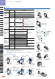
Selection
Guide
Amplifier
Built-in
EX-10
CX-400
EX-20
EX-30
EX-40
EQ-30
EQ-500
MQ-W
RX-LS200
RX
CY
PX-2
RT-610
Amplifier-
separated
Power Supply
Built-in
NX5
VF
SU-7 / SH
SS-A5 / SH
Other
Products
CX-400
Amplier
Built-in
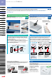
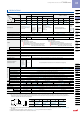
Compact Photoelectric Sensor CX-400 SERIES
240
Notes: 1) Where measurement conditions have not been specied precisely, the conditions used were an ambient temperature of +23 °C +73.4 °F.
2) The sensing range and the sensing object of the retroreective type sensor are specied for the RF-230 reector. The sensing range represents the
actual sensing range of the sensor. The sensing ranges itemized in “A” of the table below may vary depending on the shape of sensing object. Be sure
to check the operation with the actual sensing object.
3) The sensing range and the hysteresis of the diuse reective type sensor are specied for white non-glossy paper (200 × 200 mm
7.874 × 7.874 in) as
the object.
4) If slit masks (optional) are tted, an object of ø0.5 mm
ø0.020 in (using round slit mask) can be detected.
5) Make sure to conrm detection with an actual sensor before use.
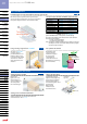
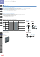
Sensor Reflector
Setting range
of the reflector: B
Sensing
object
Sensing
range: A
CX-491□ CX-493□ CX-481□ CX-482□
A
0 to 3 m
0 to 9.843 ft
0 to 5 m
0 to16.404 ft
50 to 500 mm
1.969 to 19.685 in
0.1 to 2 m
0.328 to 6.562 ft
B
0.1 to 3 m
0.328 to 9.843 ft
0.1 to 5 m
0.328 to 16.404 ft
100 to 500 mm
3.937 to 19.685 in
0.8 to 2 m
2.625 to 6.562 ft
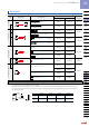
SPECIFICACTIONS
Type
Thru-beam Retroreective
Diuse reective
Long sensing range
With polarizing lters
Long sensing range
For transparent object sensing
Narrow-view
Model No.
NPN output CX-411 CX-412 CX-491 CX-493 CX-481 CX-482 CX-424 CX-421 CX-422 CX-423
Item
PNP output
CX-411-P CX-412-P CX-491-P CX-493-P CX-481-P CX-482-P CX-424-P CX-421-P CX-422-P CX-423-P
Sensing range
10 m
32.808 ft
15 m
49.213 ft
3 m
9.843 ft (Note 2)
5 m
16.404 ft (Note 2)
50 to 500 mm
1.969 to 19.685 in (Note 2)
0.1 to 2 m
0.328 to 6.562 ft (Note 2)
100 mm
3.937 in (Note 3)
300 mm
11.811 in (Note 3)
800 mm
31.496 in (Note 3)
70 to 200 mm
2.756 to 7.874 in (Note3)
Sensing object
ø12 mm ø0.472 in or
more opaque object
(Note 4)
ø50 mm
ø1.969 in or
more opaque,
translucent or
specular object
(Note 2, 5)
ø50 mm
ø1.969 in or
more opaque
or translucent
object
(Note 2, 5)
ø50 mm ø1.969 in or
more transparent,
translucent or opaque
object
(Note 2, 5)
Opaque, translucent or
transparent object (Note 5)
Opaque, translucent
or transparent
object (Note 5)
Min. sensing object:
ø0.5 mm ø0.020 in
copper wire
Hysteresis
–
15 % or less of operation distance (Note 3)
Repeatability (perpendicular to sensing axis)
0.5 mm 0.020 in or less 1 mm 0.039 in or less
0.5 mm 0.020 in or less
Supply voltage 12 to 24 V DC ± 10 % Ripple P-P 10 % or less
Current consumption
Emitter: 20 mA or less
Receiver: 20 mA or less
Emitter: 25 mA or less
Receiver: 20 mA or less
20 mA or less
25 mA or less
25 mA or less
20 mA or less
Output
<NPN output type>
NPN open-collector transistor
Maximum sink current: 100 mA
Applied voltage: 30 V DC or less (between output and 0 V)
Residual voltage: 1 V or less (at 100 mA sink current)
0.4 V or less (at 16 mA sink current)
•
•
•
<PNP output type>
PNP open-collector transistor
Maximum source current: 100 mA
Applied voltage: 30 V DC or less (between output and +V)
Residual voltage: 1 V or less (at 100 mA source current)
0.4 V or less (at 16 mA source current)
•
•
•
Output operation Switchable either Light-ON or Dark-ON
Short-circuit protection Incorporated
Response time 1 ms or less
Operation indicator Orange LED (lights up when the output is ON) (incorporated on the receiver for thru-beam type)
Stability indicator
Green LED (lights up under stable light received condition or stable dark condition) (incorporated on the receiver for thru-beam type)
Power indicator
Green LED (lights up when the power
is ON) (incorporated on the emitter)
–
Sensitivity adjuster
Continuously variable adjuster (incorporated on the receiver for thru-beam type)
Automatic interference
prevention function
Two units of sensors
can be mounted
close together
with interference
prevention lters.
(Sensing range: 5 m
16.404 ft)
–
Incorporated (Two units of sensors can be mounted close together.)
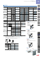
Environmental resistance
Protection IP67 (IEC) (Refer to p.984 for details of standards.)
Ambient temperature – 25 to +55 °C –13 to +131 °F (No dew condensation or icing allowed ), Storage: –30 to +70 °C –22 to +158 °F
Ambient humidity 35 to 85 % RH, Storage: 35 to 85 % RH
Ambient illuminance Incandescent light: 3,000 ℓx at the light-receiving face
EMC EN 60947-5-2
Voltage withstandability 1,000 V AC for one min. between all supply terminals connected together and enclosure
Insulation resistance 20 MΩ, or more, with 250 V DC megger between all supply terminals connected together and enclosure
Vibration resistance 10 to 500 Hz frequency, 1.5 mm 0.059 in amplitude (10 G max.) in X, Y and Z directions for two hours each
Shock resistance 500 m/s
2
acceleration (50 G approx.) in X, Y and Z directions for three times each
Emitting element (modulated) Red LED
Infrared LED
Red LED Infrared LED Infrared LED Red LED
Peak emission wavelength
680 nm 0.027 mil 870 nm 0.034 mil 680 nm 0.027 mil 650 nm 0.026 mil
870 nm 0.034 mil 860 nm 0.034 mil
645 nm 0.025 mil
Material
Enclosure: PBT (polybutylene terephthalate), Lens: acrylic (CX-48□: polycarbonate), Indicator cover: acrylic (CX-48□: polycarbonate)
Cable 0.2 mm
2
3-core (thru-beam type emitter: 2-core) cabtyre cable, 2 m 6.562 ft long
Cable extension Extension up to total 100 m 328.084 ft is possible with 0.3 mm
2
, or more, cable (thru-beam type: both emitter and receiver).
Weight
Net weight
Emitter: 45 g approx., Receiver: 50 g approx.
50 g approx.
Gross weight 100 g approx. 80 g approx. 60 g approx.
Accessory
–
RF-230 (Reector): 1 pc.
–