
User manual

Sensing object
Reflector
Sensor
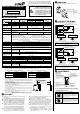
䢇 Beam alignment
Thru-beam type sensor
q Set the operation mode switch to the Light-ON
mode position (L side).
w Placing the emitter and the receiver face to face
along a straight line, move the emitter in the up,
down, left and right directions, in order to deter-
mine the range of the light received condition with
the help of the operation indicator (orange). Then,
set the emitter at the center of this range.
e Similarly, adjust for up, down, left and right angu-
lar movement of the emitter.
r Further, perform the angular adjustment for the
receiver also.
t Check that the stability indicator (green) lights up.
y Choose the operation mode, Light-ON or Dark-ON,
as per your requirement, with the operation mode
switch.
http://www.sunx.co.jp/
Head Office
2431-1 Ushiyama-cho, Kasugai-shi, Aichi, 486-0901, Japan
Phone: +81-(0)568-33-7211 FAX: +81-(0)568-33-2631
Overseas Sales Dept.
Phone: +81-(0)568-33-7861 FAX: +81-(0)568-33-8591
SUNX Limited
PRINTED IN JAPAN
Retroreflective type sensor
q Set the operation mode switch to the Light-ON
mode position (L side).
w Placing the sensor and the reflector face to face
along a straight line, move the reflector in the up,
down, left and right directions, in order to deter-
mine the range of the light received condition with
the help of the operation indicator (orange). Then,
set the reflector at the center of this range.
e Similarly, adjust for up, down, left and right angu-
lar movement of the reflector.
r Further, perform the angular adjustment for the
sensor also.
t Check that the stability indicator (green) lights up.
y Choose the operation mode, Light-ON or Dark-ON,
as per your requirement, with the operation mode
switch.
Note: Use the ‘minus’ adjusting screwdriver (please arrange
separately) to turn the adjuster slowly. Turning with ex-
cessive strength will cause damage to the adjuster.
Relation between output and indicators
n
AUTOMATIC INTERFERENCE
PREVENTION FUNCTION
(Excluding thru-beam type sensor)
䢇 Retroreflective type sensor, diffuse reflective type
sensor and narrow-view reflective type sensor in-
corporate this function. Up to two sets of sensor
can be mounted closely.
Thru-beam type sensor does not have this func-
tion.
.
INTERFERENCE PREVEN-
TION FILTER (OPTIONAL)
(Exclusively for thru-beam type sensor)
䢇 By mounting interference prevention filters
(PF-CX4-
M
), two sets of CX-411
M
can be mounted
close together.
However, the sensing range is reduced when the
interference prevention filter is mounted.
䢇 The filters can be mounted by the same method
as for the slit masks.
䢇 The two sets of sensors should be fitted with dif-
ferent types of interference prevention filters.
The interference prevention does not work even if
the filters are mounted for emitters only, receivers
only or the same model No. of the interference pre-
vention filters are mounted on both the set of the
sensor.
()
m
RETROREFLECTIVE TYPE SEN-
SOR WITH POLARIZING FILTERS
䢇 As light is polarized by a transparent film or mem-
brane, CX-491
M
may not detect an object covered
or wrapped by transparent film. In that case, take
the following steps.
(Example of sensing objects)
• Can wrapped by clear film
• Aluminum sheet covered by plastic film
• Gold or silver color (glossy) labels or wrapping
paper
(Steps)
• Tilt the sensor with respect to the sensing object
upon fitting.
• Reduce the sensitivity.
• Increase the distance between the sensor and the
sensing object.
: lights up 䢇: lights off
In case of Light-ON
In case of Dark-ON
Sensing object
Emitter
Receiver
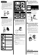
䢇 Sensitivity adjustment
Close mounting of two sensors
Fixing tab
Fixing groove
Fixing groove
Fixing hook
Removing tab
Slit mask
Fitted with
PF-CX4-V
Fitted with
PF-CX4-H
Stability
Operation
Output
Sensing
Output
Operation
Stability
indicator indicator
condition
indicator indicator
Stable light
receiving
Unstable light
receiving
Unstable dark
condition
Stable dark
condition
ON OFF 䢇
䢇
ON
䢇 OFF
䢇
Turn the sensitivity adjuster fully
counterclockwise to the minimum
sensitivity position, MIN.
()
q
w
e
r
Step
Sensitivity adjuster
Description
In the light received condition, turn the
sensitivity adjuster slowly clockwise
and confirm the point A where the sen-
sor enters the ‘Light’ state operation.
In the dark condition, turn the sensi-
tivity adjuster further clockwise until
the sensor enters the ‘Light’ state op-
eration and then bring it back to con-
firm point B where the sensor just
returns to the ‘Dark’ state operation.
If the sensor does not enter the
‘Light’ state operation even when
the sensitivity adjuster is turned
fully clockwise, the position is point
B.
The position at the middle of points
A and B is the optimum sensing
position.
A
AB
AB
Optimum position
How to mount
q Insert the fixing hook into the fixing groove.
w Then, pressing the slit mask against the main unit,
insert the fixing tab into the fixing groove.
How to remove
q Insert a screwdriver into the removing tab.
w Pull forward while lifting the removing tab.
Type Model No. Slit size
OS-CX-05
0.5mm
Round slit mask OS-CX-1
1mm
OS-CX-2
2mm
Rectangular slit
OS-CX-05
x
6 0.5 × 6mm
mask
OS-CX-1
x
6 1 × 6mm
OS-CX-2
x
6 2 × 6mm
,
SLIT MASK (OPTIONAL)
(Exclusively for thru-beam type sensor)
䢇 With the slit mask (OS-CX-
M
), the sensor can de-
tect a small object.
However, the sensing range is reduced when the
slit mask is mounted.
Thru-beam
Light received condition Dark condition
Retroreflective
ReceiverEmitter
Emitter
Sensing object
Receiver
Sensor
Reflector
Sensor
Sensing object
Reflector
Diffuse reflective
Narrow-view reflective
Sensor
Sensing object
Sensor