
Operating Instructions DVD Recorder DMR-ES35V


AUDIO
L
R
OPTICAL
OUT
VIDEO OUT
S VIDEO
OUT
COMPONENT VIDEO OUT
Y
P
P
B
R
RF OUT
RF IN
AV2(DECODER/EXT)
AV 1 (TV)
AC IN
2
4
6
10
Y
P
B
P
R
VIDEO OUT
AV1 (TV)
8
3
5
7
9
1
AUDIO OUT
L
R
AV2 (DECODER/EXT)
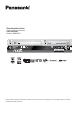
Rear Panel
5
6
7
8
9
10
4
2
3
1
9
AV1 (TV) = 21-pin Scart socket
TV connection
AV2 (DECODER/EXT) = 21-pin Scart socket
External unit connection
Y
P
P
= Luminance signal (brightness signal)
= Chrominance signal (colour difference)
= Chrominance signal (colour difference)
B
R
OPTICAL
Digital audio output
AC IN~ = Power supply
For a conventional tube television, we recommend using the Scart socket.
You retain a high-quality RGB video picture with an RGB-compatible television.
If you want to use a progressive-capable LCD/plasma television or LCD projector, connect it to COMPONENT VIDEO OUT to get a high quality
progressive video picture.
!
RF IN
Aerial input
RF OUT
Aerial output
COMPONENT VIDEO OUT
Connection for the power cable.
Audio output, right/left channel Video output
S VIDEO OUT
S VIDEO output socket
The outputs of 2, 3, 4, 7 and 8 are dedicated to modules of digital signal processing (DVD).
The video and audio outputs of 5 and 6 are dedicated to modules of digital (DVD) or analogue (VHS) signal processing.
Both groups of outputs are used for analogue and digital sources. But there are limitations, e.g.: During recording or scheduled recording on DVD, the VHS
playback is only possible on outputs of 5 and 6.