
Datasheet

DSP
7
ds_61A05_en_dsp: 070313D
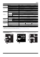
DIMENSIONS (Unit: mm inch)
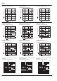
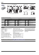
FIXING AND REMOVAL METHOD
ACCESSORIES
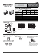
SOCKETS FOR
DS-P RELAYS
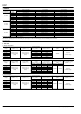
TYPES AND APPLICABLE RELAYS
SPECIFICATIONS
Type No.
Applicable relays
For DSP1a For DSP1a, DSP1, DSP2a
DSP1a-PS DSP1a-PSL2 DSP2a-PS DSP2a-PSL2
DSP1a relays OK OK OK OK
DSP1a-L2 relays OK OK
DSP1 relays OK OK
DSP1-L2 relays OK
DSP2a relays OK OK
DSP2a-L2 relays OK
Item Specifications
Breakdown voltage
3,000 Vrms between terminals
(Except for the portion between coil terminals)
Insulation resistance 1,000 M between terminals at 500 V
Heat resistance 150C for 1 hour
Max. continuous current 8 A
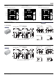
External dimensions
PC board pattern (Bottom view)
5.7±0.3
17±0.6
11±0.6
23±0.6
0.3±0.1
7.62±0.3 10.16±0.3
0.8±0.1
0.65±0.1
7.62±0.3
2.54±0.3
3.7
2.61
.224±.012
.669±.024
.433±.024
.906±.024
.012±.004
.300±.012 .400±.012
.031±.004
.026±.004
.300±.012
.100±.012
.146
.103
DSP1a-PS, DSP1a-PSL2
Terminal No.2 and 15 are for
DSP1a-PSL2 only.
DSP2a-PS, DSP2a-PSL2
Terminal No.2 and 15 are for
DSP2a-PSL2 only.
12
15 16
58
2.54
2.54
1.2 dia.
047 dia.
.100
.100
12
15 16
58
129
2.54
2.54
1.2 dia.
047 dia.
.100
.100
1. Match the direction of relay and
socket.
2. Both ends of relays are fixed so tightly
that the socket hooks on the top surface
of relays.
3. Remove the relay, applying force in the
direction shown below.
4. In case there is not enough space for
finger to pick relay up, use screw drivers
in the way shown below.
Notes: 1. Exercise care when removing relays. If
greater than necessary force is applied at
the socket hooks, deformation may alter the
dimensions so that the hook will no longer
catch, and other damage may also occur.
2. It is hazardous to use IC chip sockets.
Good No good