
Datasheet
Design and specifications are each subject to change without notice. Ask factory for the current technical specifications before purchase and/or use.
Should a safety concern arise regarding this product, please be sure to contact us immediately.
Conductive Polymer Hybrid Aluminum Electrolytic Capacitors
47
ZKE
Capacitance (µF)
Rated voltage mark
Series identification
Lot number
Negative polarity marking (–)
A±0.2
W
( ) Reference size
L
0D±0.5
H
B±0.2
(I)
K
(P)
(I)
+
–
0.3 max.
Pressure relief (010 and larger)
●
High capacitance and High ripple current compared with ZC series
●
Endurance : 4000 h at 125 °C (High temperature / Long life)
●
Low ESR (85 % over, Lower ESR than Current V-TP), Low LC (0.01 CV or 3 F)
●
Equivalent to conductive polymer type Aluminum Electrolytic Capacitor
(There are little characteristics change by temperature and frequency)
●
Vibration-proof product is available upon request. New lineup of 06.3 product. (06.3 mm and larger)
●
AEC-Q200 compliant
●
RoHS directive compliant
Speci cations
Features
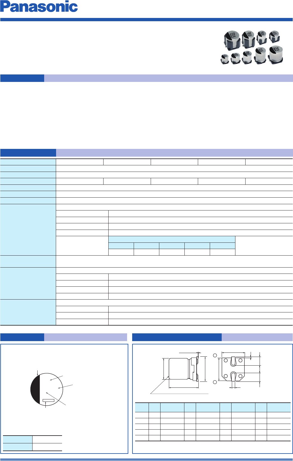
Marking Dimensions (not to scale)
Surface Mount Type
Series : ZK Type : V
High temperature Lead-Free re ow
Capacitance tolerance ±20 % (120 Hz/+20 °C)
DC leakage cur rent I
<
0.01 CV or 3 (µA) After 2 minutes (whichever is greater)
Dissipation factor (tan
d
)
Please see the attached standard products list
Endurance
125 °C, 4000 h, apply the rated ripple current without exceeding the rated voltage
Capacitance change Within ±30% of the initial value
tan
d
<
200 % of the initial limit
E. S. R.
<
200 % of the initial limit
DC leakage current Within the initial limit
ESR after Endurance
(Ω/100 kHz) (–40 °C)
Size code
CDD8FG
2.0 1.4 0.8 0.4 0.3
Shelf life
After storage for 1000 hours at +125 °C±2 °C with no voltage applied and then being stabilized at +20 °C,
capacitors shall meet the limits specifi ed in Endurance. (With voltage treatment)
Damp heat (Load)
85 °C, 85 % to 90 %, 2000 h, rated voltage applied
Capacitance change Within ±30 % of the initial value
tan
d
<
200 % of the initial limit
E. S. R.
<
200 % of the initial limit
DC leakage current Within the initial limit
Resistance to
soldering heat
After refl ow soldering and then being stabilized at +20 °C, capacitors shall meet the following limits.
Capacitance change Within ±10% of the initial value
tan
d
Within the initial limit
DC leakage current Within the initial limit
Example : 25 V.DC 47 µF Marking color : BLACK
Rated voltage mark
Size
code
D L A, B H I W P K
C 5.0 5.8±0.3 5.3 6.5 max. 2.2 0.65±0.1 1.5 0.35
- 0.20
D 6.3 5.8±0.3 6.6 7.8 max. 2.6 0.65±0.1 1.8 0.35
- 0.20
D8 6.3 7.7±0.3 6.6 7.8 max. 2.6 0.65±0.1 1.8 0.35
- 0.20
F 8.0 10.2±0.3 8.3 10.0 max. 3.4 0.90±0.2 3.1 0.70±0.2
G 10.0 10.2±0.3 10.3 12.0 max. 3.5 0.90±0.2 4.6 0.70±0.2
+ 0.15
+ 0.15
+ 0.15
E 25 V.DC
V 35 V.DC
(Unit : mm)
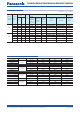
Size code
CDD8FG
Category temp. range
–55 °C to +125 °C
Rated voltage range
25 V.DC to 35 V.DC
Nominal cap.range
33 µF to 47 µF 56 µF to 68 µF 100 µF to 150 µF 180 µF to 270 µF 330 µF to 470 µF
·
The dimensions of the vibration-proof products, please refer to the page of
the mounting specifi cation.
Nov. 201702