
Datasheet


Design and specifi cations are each subject to change without notice. Ask factory for the current technical specifi cations before purchase and/or use.
Should a safety concern arise regarding this product, please be sure to contact us immediately.
Metal Film Chip Resistors, Rectangular Type
Chip Resistor
c
a
b
Preheating
Peak
Heating
Temperature
Time
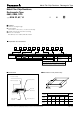
Type
(inches)
Dimensions (mm)
abc
ERA3Y
(0603)
0.7 to 0.9 2 to 2.2 0.8 to 1
ERA6Y
(0805)
1 to 1.4 3.2 to 3.8 0.9 to 1.4
ERA14
(1210)
2 to 2.4 4.4 to 5.0 1.8 to 2.8
Temperature Time
Preheating 140 °C to 160 °C 60 s to 120 s
Main heating Above 200 °C 30 s to 40 s
Peak 235 ± 5 °C max. 10 s
Temperature Time
Preheating 150 °C to 180 °C 60 s to 120 s
Main heating Above 230 °C 30 s to 40 s
Peak max. 260 °C max. 10 s
For soldering For lead-free soldering
Temperature TimeTemperatureTime
Preheating 140 °C to 180 °C 60 s to 120 s 150 °C to 180 °C 60 s to 120 s
Soldering 245 ± 5 °C 20 s to 30 s max. 260 °C max. 10 s
■ Recommended Soldering Conditions
Recommendations and precautions are described below.
●
Recommended soldering conditions for refl ow
For soldering (Example : Sn/Pb)
For lead-free soldering (Example : Sn/Ag/Cu)
●
Recommended soldering conditions for fl ow
In case of fl ow soldering, the land width must be small er than the Chip Resistor width to properly control the sol der amount
properly. Generally, the land width should be 0.7 to 0.8 times (W) of the width of chip resistor. In case of refl ow soldering,
solder amount can be adjusted, there fore the land width should be set to 1.0 to 1.3 times chip resistor width (W).
■ Recommended Land Pattern
Safety Precautions
The following are precautions for individual products. Please also refer to the precautions common to Fixed Resistors
shown on page ER3 of this catalog.
1. Keep the rated power and ambient temperature within the specifi ed derating curve.
* When positioning and mounting Metal Film Chip Resistors (hereafter called the resistors), make allowance for the
effect of heat generated through close contact between the resistors and neigh bor ing components and for the
temperature rise of adjacent heat-generating components.
2. If a transient load (heavy load in a short time) like a pulse is expected to be applied, check and evaluate the operations
of the resistors when installed in your products before use.
When applying pulses to the resistors, keep the pulse peak within the rated voltage.
3. Do not use halogen-based or other high-activity fl ux. Otherwise, the residue may impair the resistors' per for mance
and/or reliability.
4. When soldering with a soldering iron, never touch the resistors' bodies with the tip of the soldering iron. When using a
soldering iron with a high temperature tip, fi nish soldering as quickly as possible (within three seconds at 350 °C max.).
5. As the amount of applied solder becomes larger, the mechanical stress applied to the resistors increases, causing
problems such as cracks and faulty characteristics. Avoid applying an excessive amount of solder.
6. When the resistors' protective coatings are chipped, fl awed, or removed, the characteristics of the resistors may be
impaired. Take special care not to apply mechanical shock during automatic mounting or cause damage during
handling of the boards with the resistors mounted.
7. Do no t apply shock to the resistors or pinch them with a hard tool (e.g. pliers and tweezers). Otherwise, the resistors'
protective coatings and bodies may be chipped, affecting their performance.
8. Avoid excessive bending of printed circuit boards in order to protect the resistors from abnormal stress.
9. Do not immerse the resistors in solvent for a long time. Before using solvent, carefully check the effects of im mer sion.
· Refl ow soldering shall be performed a maximum of
two times.
· Please contact us for additional information when
used in conditions other than those specifi ed.
· Please measure the temperature of the terminals
and study every kind of solder and printed circuit
board for solderability be fore ac tu al use.
Feb. 2006