
Datasheet


FIBER
SENSORS
LASER
SENSORS
PHOTO-
ELECTRIC
SENSORS
MICRO
PHOTO-
ELECTRIC
SENSORS
AREA
SENSORS
SAFETY
COMPONENTS
PRESSURE
SENSORS
INDUCTIVE
PROXIMITY
SENSORS
PARTICULAR
USE
SENSORS
SENSOR
OPTIONS
WIRE-
SAVING
SYSTEMS
MEASURE-
MENT
SENSORS
STATIC
CONTROL
DEVICES
LASER
MARKERS
INDUCTIVE
PROXIMITY
SENSORS
Selection
Guide
Amplifier
Built-in
GXL
GX-F/H
GL
GX-U / GX-FU /
GX-N
GX
GA-311 / GH
Other
Products
Amplifier-
separated
GX-F
/
/H
Amplifi er
Built-in
655
Rectangular-shaped Inductive Proximity Sensor GX-F/H SERIES
PRECAUTIONS FOR PROPER USE
Refer to p.1012 ~ for general precautions.
Mounting
GX-8 type
Never use this product as a sensing device
for personnel protection.
In case of using sensing devices for
personnel protection, use products which
meet laws and standards, such as OSHA,
ANSI or IEC etc., for personnel protection
applicable in each region or country.
•
•
Make sure to use a M3
(length: 12 mm
0.472 in or
more) truss head screw.
The tightening torque
should be 0.7 N·m or less.
Do not use a fl at head
screw or a pan head
screw.
•
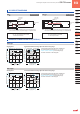
Infl uence of surrounding metal
When there is a metal near the sensor, keep the minimum
separation distance specifi ed below.
•
Front sensing type
GX-F8□ GX-F12□
A 7.4 mm 0.291 in 7.1 mm 0.280 in
B 8 mm 0.315 in 20 mm 0.787 in
C 3 mm 0.118 in 7 mm 0.276 in
Top sensing type
GX-12 type
The tightening torque
should be 0.7 N·m or less.
To mount the sensor with
a nut, the mouting hole
diameter should be ø3.4
mm
ø0.134 in. Further, the
hole in which the boss is
inserted should be ø2.5
mm
ø0.098 in and 3 mm
0.118 in, or more, deep.
•
•
GX-H8□ GX-H12□
D 4 mm 0.157 in 7 mm 0.276 in
E 10 mm 0.394 in 20 mm 0.787 in
F 3 mm 0.118 in 3 mm 0.118 in
G 3 mm 0.118 in 3 mm 0.118 in
M3 (length 12 mm 0.472 in or more)
pan head screw
(Please arrange separately.)
M3 × 0.5 mm 0.020 in tapped hole
(Depth: 10 mm 0.394 in or more)
or ø3.4 mm ø0.134 in thru-hole
If mounting using nut
and washers
(Please arrange separately.)
16 mm 0.630 in
ø2.5 mm ø0.098 in hole
(Depth: 3 mm 0.118 in or more)
Metal
A
Metal Metal
C
C
B
G
G
Metal
Metal
Metal
E
F
D
Metal
Mutual interference prevention
When two or more sensors are installed in parallel or face
to face, keep the minimum separation distance specifi ed
below to avoid mutual interference.
•
Front sensing
Top sensing
HJ
GX-F8□
Between “I” type
and non “I” type
0 mm
(Note 2)
15 mm
0.591 in
Between two “I” types
or two non “I” types
20 mm
0.787 in
35 mm
1.378 in
GX-H8□
Between “I” type
and non “I” type
0 mm
(Note 2)
15 mm
0.591 in
Between two “I” types
or two non “I” types
20 mm
0.787 in
35 mm
1.378 in
GX-F12□
GX-H12□
Between “I” type
and non “I” type
0 mm
(Note 2)
25 mm
0.984 in
Between two “I” types
or two non “I” types
25 mm
0.984 in
50 mm
1.969 in
H
H
J
Sensing range
The sensing range is specifi ed for the standard sensing
object. With a non-ferrous metal, the sensing range is
obtained by multiplying with the correction coeffi cient
specifi ed below. Further, the sensing range also changes
if the sensing object is smaller than the standard sensing
object or if the sensing object is plated.
•
Correction coeffi cient
Model
No.
Metal
GX-8 type GX-12 type
Iron 1 1
Stainless steel
(SUS304)
0.76 approx. 0.79 approx.
Brass 0.50 approx. 0.56 approx.
Aluminum 0.48 approx. 0.53 approx.
Others
The output does not incorporate a short-circuit protection
circuit. Do not connect it directly to a power supply or a
capacitive load.
Do not use during the initial transient time (50 ms) after
the power supply is switched on.
•
•
M3 (length 12 mm 0.472 in) truss head
screw(Accessory for MS-GXL8-4)
M3 × 0.5 mm 0.020 in tapped hole
(Depth: 8 mm 0.315 in or more)
or ø3.4 mm ø0.134 in thru-hole
If mounting using nut
and washers
(Accessories for MS-GXL8-4)
ø2.4 mm ø0.098 in hole
(Depth: 3 mm 0.315 in or more)
MS-GXL8-4 (Accessory)
11.5 mm 0.453 in
H
J
Notes: 1) “I” in the model No. specifi es
the different frequency type.
2) Close mounting is possible for up
to two sensors.
When mounting three sensors or more at
an equal spacing, align the model with “I”
and the model without “I” alternately. The
minimum value of dimension “H” should
be as given below.
GX-8 type: 6mm
0.236 in
GX-12 type: 6.5mm 0.256 in