
Datasheet


FIBER
SENSORS
LASER
SENSORS
PHOTO-
ELECTRIC
SENSORS
MICRO
PHOTO-
ELECTRIC
SENSORS
AREA
SENSORS
SAFETY
COMPONENTS
PRESSURE
SENSORS
INDUCTIVE
PROXIMITY
SENSORS
PARTICULAR
USE
SENSORS
SENSOR
OPTIONS
WIRE-
SAVING
SYSTEMS
MEASURE-
MENT
SENSORS
STATIC
CONTROL
DEVICES
LASER
MARKERS
INDUCTIVE
PROXIMITY
SENSORS
Selection
Guide
Amplifier
Built-in
GXL
GX-F/H
GL
GX-U / GX-FU /
GX-N
GX
GA-311 / GH
Other
Products
Amplifier-
separated
GX-F
/
/H
Amplifi er
Built-in
Rectangular-shaped Inductive Proximity Sensor GX-F/H SERIES
656
MS-GXL8-4
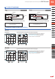
DIMENSIONS (Unit: mm in)
The CAD data in the dimensions can be downloaded from the SUNX website: http://www.sunx.com
8
0.315
23
0.906
22.5
0.886
11. 5
0.453
6.5
0.256
5.4
0.213
6.3
0.248
ø9 ø0.354
ø3.1 ø0.12
mounting hole
ø3 ø0.118 cable,
1 m 3.281 ft long
8.55
0.337
7.4
0.291
2.95
0.116
7.7
0.303
9.75
0.384
2.65
0.104
5
0.197
5.3
0.209
Operation indicator
(Orange)
Sensing
direction
1
0.039
Sensor
GX-F8□
Sensor
GX-H8□
Sensor
GX-F12□
Operation indicator
(Orange)
ø2.3
ø0.091
16
0.630
2.8
0.110
3.3 0.130
12.4
0.488
11.05
0.435
1.5 0.059
5.6
0.221
5.2
0.205
7.1
0.280
12
0.472
ø12.5 ø0.492
27.8
1.095
4.4 0.173
ø6 ø0.236 screw seat,
0.8 0.032 deep
12
0.472
16
0.630
27
1.063
7.8
0.307
6.8
0.268
ø3.1 ø0.12
mounting hole
ø3 ø0.118 cable,
1 m 3.281 ft long
5 0.197
Sensing
direction
3.7
0.146
R4.25
R0.167
4.6
0.181
8.2 0.323
8.6
0.339
18.5
0.728
6.8
0.268
3.85
0.152
9.1 0.358
2 0.079
2.5
0.098
25
0.984
1
0.039
2.4
0.095
4.8 0.189
5.3 0.209
Sensing
direction
Operation indicator (Orange)
ø3.1 ø0.122 mounting hole
5.4 0.213 6.3 0.248
ø3 ø0.118 cable,
1 m 3.281 ft long
8
0.315
Sensor
GX-H12□
12.5
0.492
12
0.472
7.8
0.307
4.8 0.189
3.1
0.12
5.8
0.228
6.2
0.244
8.65 0.341
Operation indicator
(Orange)
ø2.3
ø0.091
1.5
0.059
22.2
0.874
12
0.472
ø6 ø0.236 screw seat,
1.4 0.055 deep
16
0.630
27.4
1.079
6.8 0.268
ø3.1 ø0.122 mounting hole
ø3 ø0.118 cable,
1 m 3.281 ft long
Sensing
direction
6.5 0.256
5.5
0.217
13
0.512
R6.25 R0.246
2.5
0.098
3 0.118
4.4
0.173
Sensor mounting bracket for GX-8 type (optional)
Mounting hole dimensions
Material: Stainless steel (SUS304)
1 pc. each of M3 (length 12 mm 0.472 in) truss head screw,
nut, spring washer and plain washer are attached.
2
0.079
2
0.079
2.3
0.091
0.3
0.012
ø2.4 ø0.094 hole,
3 0.118 or more deep
M3 × 0.5 0.020
tapped hole,
8 0.315 or more deep
t 0.4
t 0.016
ø3.1 ø0.122 hole
Center of
sensing
3.3
0.130
(16.2)
(0.638)
15.8
0.622
9
0.354
11.5
0.453
(11.5)
(0.453)
4.5 0.177