
Datasheet


Rectangular-shaped Inductive Proximity Sensor GX-F/H SERIES
772
Selection
Guide
Amplier
Built-in
Amplier-
separated
GX-F/H
GXL
GL
GX-U/GX-FU/
GX-N
GX
FIBER
SENSORS
LASER
SENSORS
PHOTO-
ELECTRIC
SENSORS
MICRO
PHOTO-
ELECTRIC
SENSORS
AREA
SENSORS
LIGHT
CURTAINS
PRESSURE /
FLOW
SENSORS
INDUCTIVE
PROXIMITY
SENSORS
PARTICULAR
USE
SENSORS
SENSOR
OPTIONS
SIMPLE
WIRE-SAVING
UNITS
WIRE-SAVING
SYSTEMS
MEASURE-
MENT
SENSORS
STATIC
CONTROL
DEVICES
ENDOSCOPE
LASER
MARKERS
PLC /
TERMINALS
HUMAN
MACHINE
INTERFACES
ENERGY
CONSUMPTION
VISUALIZATION
COMPONENTS
FA
COMPONENTS
MACHINE
VISION
SYSTEMS
UV
CURING
SYSTEMS
SENSING CHARACTERISTICS (TYPICAL)
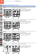
Sensing eld Correlation between sensing object size and sensing range
As the sensing object size becomes smaller than
the standard size (iron sheet 30 × 30 × t 1 mm
1.181 × 1.181 × t 0.039 in), the sensing range
shortens as shown in the left gure.
0
0
Setting distance L (mm in)
5
0.197
5
0.197
10
0.394
10
0.394
10
0.394
5
0.197
Top
sensing
Operating point ℓ (mm in)
Center RightLeft
L
ℓ
L
ℓ
Standard sensing object
Iron sheet 30 × 30 × t 1 mm
1.181 × 1.181 × t 0.039 in
Standard sensing object
Iron sheet 30 × 30 × t 1 mm
1.181 × 1.181 × t 0.039 in
Front
sensing
t 1mm
L
L
t 1mm
t 0.039 in
t 0.039 in
Sensing object side
length a (mm in)
Sensing range L (mm in)
10
0.394
10
0.394
5
0.197
20
0.787
30
1.181
40
1.575
0
Top sensing
Iron
Stainless steel
(
SUS304
)
Brass
Front sensing
Sensing object
a
×
a mm a
×
a in
Sensing object
a
×
a mm a
×
a in
Aluminum
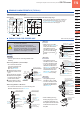
GX-15 (Long sensing range) type
PRECAUTIONS FOR PROPER USE
Refer to General precautions.
• Never use this product as a sensing device
for personnel protection.
• In case of using sensing devices for
personnel protection, use products which
meet laws and standards, such as OSHA,
ANSI or IEC etc., for personnel protection
applicable in each region or country.
• Use the optional sensor mounting bracket when
installing.
<When using MS-GX6-1 (recommended)>
• To mount the sensor with
a nut, the mounting hole
diameter should be
ø3.4 mm ø0.134 in.
1
Insert the sensor into the
bracket as shown on the
right.
2
Push the sensor until the
bracket hook is lodged in
the groove on the upper
portion of the sensor.
3
Fix the bracket in place
with M3 pan head screw.
Mounting
22 mm 0.866 in
MS-GX6-1
M3 pan head screw
(
Purchase separately
.)
ø
3.4 mm
ø
0.134 in hole
Groove
Hook
Cable
M3 x 0.5 mm 0.020 in
tapped hole or
ø3.4 mm ø0.134 in hole
If mounting using nut
and washers
(
Purchase separately
.)
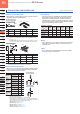
<When using MS-GL6-1 / MS-GL6-2>
• To mount the sensor with a nut, the mounting hole
diameter should be ø3.4 mm ø0.134 in.
MS-GL6-1
MS-GL6-2
ø2.4 mm
0.098 in hole
10 mm
0.394 in
13.6 mm
0.535 in
M3 pan head screws
(Purchase separately.)
M3 pan head screw
(Purchase separately.)
M3 x 0.5 mm 0.020 in
tapped holes or
ø3.4 mm ø0.134 in holes
M3 x 0.5 mm 0.020 in
tapped hole or
ø3.4 mm ø0.134 in hole
If mounting using nuts
and washers
(Purchase separately.)
If mounting using nut
and washers
(Purchase separately.)
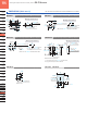
GX-8 type
• Make sure to use a M3
(length: 12 mm 0.472 in or
more) truss head screw.
The tightening torque
should be 0.7 N·m or less.
Do not use a at head
screw or a pan head
screw.
GX-12 type
GX-6 type
GX-15 type
• The tightening torque
should be 0.7 N·m or less.
• To mount the sensor with
a nut, the mounting hole
diameter should be ø3.4
mm ø0.134 in. Further, the
hole in which the boss is
inserted should be ø2.5
mm ø0.098 in and 3 mm
0.118 in, or more, deep.
• The tightening torque
should be 1 N·m or less.
• To mount the sensor with
a nut, the mounting hole
diameter should be ø3.4
mm ø0.134 in.
M3 (length 12 mm 0.472 in or more)
pan head screw
(Purchase separately.)
M3 × 0.5 mm 0.020 in
tapped hole
(Depth: 10 mm 0.394 in or more)
or ø3.4 mm ø0.134 in thru-hole
If mounting using nut
and washers
(Purchase separately.)
16 mm 0.630 in
ø2.5 mm ø0.098 in hole
(Depth: 3 mm 0.118 in or more)
M3 (length 12 mm 0.472 in) truss head
screw (Accessory for MS-GXL8-4)
M3 × 0.5 mm 0.020 in tapped hole
(Depth: 8 mm 0.315 in or more)
or ø3.4 mm ø0.134 in thru-hole
If mounting using nut
and washers
(Accessories for MS-GXL8-4)
ø2.4 mm ø0.098 in hole
(Depth: 3 mm 0.315 in or more)
MS-GXL8-4 (Accessory)
11.5 mm 0.453 in
• When installing the long
sensing range type on iron
or stainless steel plate, put
the optional aluminum sheet
in between the sensor and
the plate.
Aluminum sheet (Optional)
• MS-A15F
• MS-A15H
M3 pan head screws or
truss head screws
Do not use flat head
screws.
M3 x 0.5 mm 0.020 in
tapped holes or
ø3.4 mm ø0.134 in holes
If mounting using nuts
and washers
(Purchase separately.)
(Sensor mounting bracket)
MS-GXL15
9 mm
0.354 in