01. 英(表1-25) 05.5.18 10:38 ページ1 Operating Instructions Camera-Recorder Model No. AJ- P Before operating this product, please read the instructions carefully and save this manual for future use.
01. 英(表1-25) 05.5.18 10:38 ページ2 CAUTION: TO REDUCE THE RISK OF ELECTRIC SHOCK, DO NOT REMOVE COVER (OR BACK). NO USER SERVICEABLE PARTS INSIDE. REFER TO SERVICING TO QUALIFIED SERVICE PERSONNEL. The lightning flash with arrowhead symbol, within an equilateral triangle, is intended to alert the user to the presence of uninsulated “dangerous voltage” within the product’s enclosure that may be of sufficient magnitude to constitute a risk of electric shock to persons.
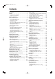
01. 英(表1-25) 05.5.18 10:38 ページ3 Contents Introduction . . . . . . . . . . . . . . . . . . . . . . . . . . . . . . .5 Features . . . . . . . . . . . . . . . . . . . . . . . . . . . . . . . . . .5 Features of the camera unit . . . . . . . . . . . . . . . . . .5 Features of the VTR unit . . . . . . . . . . . . . . . . . . . .7 System configuration . . . . . . . . . . . . . . . . . . . . . . .8 Parts and their functions . . . . . . . . . . . . . . . . . . . .9 Power supply section . . . . . . . . . . . . . . .
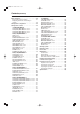
01. 英(表1-25) 05.5.18 10:38 ページ4 Contents (continued) Menu operations . . . . . . . . . . . . . . . . . . . . . . . . . .86 Basic setting menu operations . . . . . . . . . . . . . . .87 Displaying sub-menus and deciding on settings . . . . . . . . . . . . . . . . . . . . . . . . . . . . . . . . .88 Setting menu configuration . . . . . . . . . . . . . . . . .89 Setting menu screens . . . . . . . . . . . . . . . . . . . . . .93 FILM (CAM) MAIN MENU 1 screen . . . . . . . . . . .
01. 英(表1-25) 05.5.18 10:38 ページ5 Introduction The AJ-HDC27H is a camera-recorder that supports the SMPTE-296M 1280a720 scanning standard. Integrated in this single unit are an HD color video camera featuring a 1-million pixel IT-CCD unit with onchip lens as the pickup device, and a DVCPRO HD format VTR incorporating the latest compression technology.
01. 英(表1-25) 05.5.18 10:38 ページ6 Features (continued) Features of the camera unit Prime lens mode Not only the lens that does justice to the sensitivity equivalent to a film but also the various devices and equipment that are peripheral to the camera combine to play roles which are so critical that they cannot be divorced from the technical skills of the person operating the camera.
01. 英(表1-25) 05.5.18 10:38 ページ7 Features (continued) Features of the VTR unit Digital system The pictures are compressed by a component digital recording system that uses the latest compression technology while non-compression PCM recording featuring excellent signal-to-noise ratio, frequency band, waveform characteristics and reproduction of detailed areas is employed for the sound. The result is an even higher picture and sound quality.
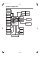
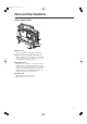
01. 英(表1-25) 05.5.18 10:38 ページ8 System configuration Microphone kit AJ-MC700P Battery case AU-M402H BP-type battery Sony Battery case Sony Battery 2.
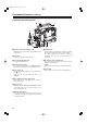
01. 英(表1-25) 05.5.18 10:38 ページ9 Parts and their functions Power supply section 1 4 2 3 1 Battery mount This is for attaching the Anton/Bauer battery pack. 2 DC IN (external power input) socket (XLR, 4P) When operating this unit using an AC power source, this socket is connected to the model AJB75 AC adapter (optional accessory). 3 BREAKER button To protect the equipment, the circuit breaker is tripped when an overcurrent flows inside the unit, and the power is automatically turned off.
01. 英(表1-25) 05.5.18 10:38 ページ10 Parts and their functions (continued) Accessory mounting section 1 2: 1 5 6 3 4 6 8 7 1 Hooks for attaching shoulder strap Attach the ends of the accessory shoulder strap to these hooks. 2 Light shoe Use this to attach the video light, etc. 3 Lens mount (Bayonet type) Use this to attach the lens. 4 Lever for securing lens Insert the lens into the lens mount 3, and turn the lens mount ring using this lever to secure the lens.
01. 英(表1-25) 05.5.18 10:38 ページ11 Parts and their functions (continued) Audio function section (1) 2 3 4 6 1 7 5 1 MIC IN (microphone input) jack (XLR, 3-pin) Connect the microphone (optional accessory) here. The power for the microphone is supplied from this jack. 5 AUDIO IN CH1/CH2 (audio input channel 1 & 2) connectors (XLR, 3-pin) An audio component or microphones are connected here.
01. 英(表1-25) 05.5.18 10:38 ページ12 Parts and their functions (continued) Audio function section (2) < Speaker The EE sound during recording or the playback sound during playback can be monitored through this speaker. The warning alarms are output in synchronization with the flashing or lighting of the warning lamps and warning displays. The sound heard from the speaker is automatically cut off when the earphone is connected to the PHONES jack ?.
01. 英(表1-25) 05.5.18 10:38 ページ13 Parts and their functions (continued) Viewfinder section = > ;7 9 : < 1 452 3 6 8 ON OFF (For details concerning the viewfinder, refer to the operating instructions of the viewfinder.) 1 Viewfinder (optional accessory) While recording or playback is underway, pictures can be viewed through the viewfinder in black and white.
01. 英(表1-25) 05.5.
01. 英(表1-25) 05.5.18 10:38 ページ15 Parts and their functions (continued) Shooting (recording)/playback function section (2) 6 5 4 4 OUTPUT (output signal selector)/AUTO KNEE switch This is used to select the video signals which are to be output from the camera unit to the VTR unit, viewfinder and video monitor. The operation of the AUTO KNEE function can be selected using the AUTO KNEE SW item on the CAMERA SW MODE screen of FILM (CAM) MAIN MENU 2.
01. 英(表1-25) 05.5.18 10:38 ページ16 Parts and their functions (continued) Shooting (recording)/playback function section (3) 9 7 7 SHUTTER switch This is set to ON when the electronic shutter is to be used. When the SEL side is pressed, the shutter speed and mode display are changed in the range which was set ahead of time in the setting menu. If this switch setting is changed while the display mode is set to “2” or “3,” the new setting will appear at the shutter display position on the viewfinder screen.
01. 英(表1-25) 05.5.18 10:38 ページ17 Parts and their functions (continued) Shooting (recording)/playback function section (4) ; = > ; MONITOR OUT switch This is used to select the video and audio signals which are to be output from the HD SDI MON connector and the audio signals which are to be output from the AUDIO OUT connectors. EE/PB : During playback, the playback video and playback audio signals are output; in all other modes, the EE video and EE audio signals are output.
01. 英(表1-25) 05.5.18 10:38 ページ18 Parts and their functions (continued) Shooting (recording)/playback function section (5) D A B C E ? @ ? MODE CHECK button While this button is held down, the camera’s setting mode is shown in the viewfinder. This does not affect the output signals of the camera. @ USER 1 and USER 2 buttons A user setting can be allocated to each of these buttons using the setting menu. When a button is pressed, the user setting mode allocated to it is selected.
01. 英(表1-25) 05.5.18 10:38 ページ19 Parts and their functions (continued) Warning/status display section 4 1 2 3 5 1 Back tally lamp (unit) When the back tally switch 2 is set to ON, this lamp serves the same function as the front tally lamp in the viewfinder. 2 Back tally switch This is used to control the unit’s back tally lamp 1. ON : The unit’s back tally lamp is operational. OFF : The unit’s back tally lamp is not operational.
01. 英(表1-25) 05.5.18 10:38 ページ20 Parts and their functions (continued) Menu operation section 3 JOG dial button When this dial button is turned while the menu screen is displayed, the cursor is moved to each of the setting items. The menu items are set by operating this dial button. There are two types of menus, MAIN and SUB, and each menu is displayed on a page-by-page basis. The menu configuration can be changed to suit the desired objective.
01. 英(表1-25) 05.5.18 10:38 ページ21 Parts and their functions (continued) Time code related section (2) 46 5 9 8 7 4 HOLD button The time data display of the counter display section which was on the screen at the moment when this button is pressed is held. (However, the time code generator keeps running.) When the button is pressed again, the hold status is released. It is used, for instance, to find out the time at which a particular scene was shot.
01. 英(表1-25) 05.5.18 10:38 ページ22 Power supply A battery pack or an AC power source can be used as this unit’s power supply. To use the battery pack, there is a choice of makes of batteries below, namely: OPanasonic OAnton/Bauer OIDX OSony Using the Anton/Bauer battery pack the battery pack. 1 Attach Insert the pack in the direction shown by the arrows, and then slide it into position.
01. 英(表1-25) 05.5.18 10:38 ページ23 Power supply (continued) Using the Panasonic battery pack 1 Remove the battery holder. the plug on the battery pack to the 3 Connect connector inside the case, and insert the battery pack. the battery case to the unit. 2 Attaching 1 Connect the cable on the camera-recorder to the cable on the battery case (BP-90 type). 2 Using a screwdriver, secure the battery case (BP-90 type) to the camera-recorder.
01. 英(表1-25) 05.5.18 10:38 ページ24 Power supply (continued) Using the Sony battery pack 1 Remove the battery holder. 2 Attach the accessory battery mounting connector. Using the V-mount type battery pack Attach the V-mount adapter plate. Insert it in the direction shown by the arrows, and slide it into place. Battery mounting connector 3 Attach the Sony battery case to the unit. 1 Tighten the mounting screws. 2 Tighten the power contact screws.
01. 英(表1-25) 05.5.18 10:38 ページ25 Power supply (continued) Using an AC power supply (When the AJ-B75 AC adapter is used) the DC OUT connector on the AJ-B75 AC 1 Connect adapter to the DC IN socket on the unit. DC IN socket 2 Set the power of the AC adapter to ON. 3 Set the unit’s power switch to ON. O Check the pin signals of the DC IN socket when using an external power supply other than the AJB75 AC adapter. (DC 12 V, 8.
02. 英(P26-88) 05.5.18 10:42 ページ26 Attaching the lens the lever for securing the lens, and detach the cable into the cable clamp, and connect it 1 Raise 4 Push the mount cap. to the LENS socket. Lever for securing the lens Mount cap LENS socket the center mark of the lens with the groove in 2 Align the top center of the lens mount, and attach the lens. Mark down the lever for securing the lens to 3 Push secure the lens.
02. 英(P26-88) 05.5.18 10:42 ページ27 Adjusting the lens flange If the subject is not focused properly in the telephoto and wide-angle modes during zoom operations, adjust the flange back (distance from the lens mounting surface to the image-forming surface). Once this adjustment is done, it need not be redone unless the lens is replaced. Adjustment method For details on the adjustment method and lens positions, refer also to the operating instructions that accompany the lens. Approx.
02. 英(P26-88) 05.5.18 10:42 ページ28 Adjusting the white shading This unit comes with a function for storing white shading adjustment values. Up to eight of these values can be stored in the internal memory. Alternatively, they can be stored on an SD memory card. Using this data, it is possible to quickly reproduce the appropriate white shading adjustment even after switching lenses. O The method below can be used for the white shading adjustments with most lenses.
02. 英(P26-88) 05.5.18 10:42 ページ29 Adjusting the white shading (continued) Performing white shading adjustments 15 Repeat step 13. 11 Set the ZEBRA switch on the viewfinder to ON. the menu operations (pages 86 to 88), 16 Perform and display the “WHITE SHADING” screen of a sheet of white paper devoid of colour 12 Shoot irregularities.
02. 英(P26-88) 05.5.18 10:42 ページ30 Adjusting the white shading (continued) lens is provided with an extender, engage 21 Ifthetheextender function, and repeat steps 13 to 20. The compensation values for when the lens extender function is provided and for when it is not are both stored in one file in memory. The white shading adjustment is now complete.
02. 英(P26-88) 05.5.18 10:42 ページ31 Adjusting the white shading (continued) Writing the white shading adjustment values and flare adjustment values in the internal memory the JOG dial button is pressed, the arrow 6 When (cursor) moves to the title input area, and the input mode is established. Up to eight white shading adjustment values can be stored in the internal memory.
02. 英(P26-88) 05.5.18 10:42 ページ32 Adjusting the white shading (continued) the JOG dial button is pressed, the arrow 11 When (cursor) returns to the TITLE: item. < LENS FILE > FILE SELECT READ WRITE RESET ALL :1 n TITLE:222222222222 1: 2: 3: 4: 5: 6: 7: 8: the JOG dial button to move the arrow 12 Turn (cursor) to the WRITE position. < LENS FILE > n FILE SELECT READ WRITE RESET ALL :1 TITLE:222222222222 1: 2: 3: 4: 5: 6: 7: 8: the JOG dial button is pressed, the 13 When following message appears.
02. 英(P26-88) 05.5.18 10:42 ページ33 Adjusting the white shading (continued) Reading the white shading adjustment values and flare adjustment values from the internal memory the menu operations (pages 86 to 88), 1 Perform and display the “LENS FILE” screen of FILM (CAM) MAIN MENU 3. the JOG dial button to move the arrow 2 Turn (cursor) to the FILE SELECT item the JOG dial button to move the arrow 7 Turn (cursor) to YES, and press the JOG dial button. The recorded data from the white shading file is read.
02. 英(P26-88) 05.5.18 10:42 ページ34 Adjusting the viewfinder (The viewfinder is an optional accessory.) Attaching the viewfinder and adjusting its position The viewfinder’s position can be adjusted in the frontback and left-right directions so that what appears on its screen inside can be seen most easily. Attaching the viewfinder and adjusting its position 1 Connect the viewfinder’s plug to the viewfinder connector. Adjusting the viewfinder’s front-back position the viewfinder 1 Loosen anchoring ring.
02. 英(P26-88) 05.5.18 10:42 ページ35 Audio input preparation When attaching a microphone to the viewfinder (optional accessory) for use The microphone of the AJ-MC700P mic kit (optional accessory) can be attached to the viewfinder. 1 Open the mic holder. the AUDIO IN switch or switches to “FRONT” 4 Set in accordance with the audio channel or channels whose sound is to be recorded. AJ-HVF27BP Mic holder the microphone, and tighten the locking 2 Attach screw.
02. 英(P26-88) 05.5.18 10:42 ページ36 Audio input preparation (continued) When attaching a microphone to the main unit for use Attaching the AJ-MH800G mic holder (optional accessory) 1 Remove the screws used to attach the mic holder. the microphone’s connecting cable to the 5 Connect MIC IN jack on the camera.
02. 英(P26-88) 05.5.18 10:42 ページ37 Audio input preparation (continued) When connecting a microphone to the MIC IN jack When connecting a microphone to the AUDIO IN connector the microphone’s connecting cable to the the microphone’s connecting cable to the 1 Connect 1 Connect MIC IN jack on the camera. AUDIO IN connector on the camera. Two microphones can be connected to the CH1 and CH2 connectors.
02. 英(P26-88) 05.5.18 10:42 ページ38 Audio input preparation (continued) When connecting audio components the AUDIO IN connectors on the camera 1 Connect with the audio component using the XLR cable. AUDIO IN connectors the AUDIO IN switch or switches for the 2 Set channel or channels to which the audio component has been connected to “REAR.” the LINE/MIC/+48V selector switch on the rear 3 Set panel to “LINE.
02. 英(P26-88) 05.5.18 10:42 ページ39 Mounting the unit on a tripod Use the tripod adapter available as an optional accessory for mounting the unit onto a tripod. the tripod adapter to the tripod. 1 Attach Select the adapter holes that best support the center of gravity of the unit and tripod adapter. Check that the diameters of the selected holes match the diameters of the pan head.
02. 英(P26-88) 05.5.18 10:42 ページ40 Attaching the shoulder strap the shoulder strap to the shoulder strap 1 Attach mounting hooks, and adjust the length of the strap. To detach the shoulder strap, open the clips on the mounting parts and detach. Check that the shoulder strap is securely fastened. The clip opens when it is pressed here. Shoulder strap The clip opens when it is pressed here. This mounting hook is for attaching the tape measure that is used to measure the subject distance.
02. 英(P26-88) 05.5.18 10:42 ページ41 Attaching the rain cover Example showing use of the SHANRC700 rain cover Tighten the cord. Close using the fastener. Close using the fastener. Connecting the extension control unit By connecting the AJ-EC3 extension control unit (optional accessory), some of the functions can be operated by remote control. When the AJ-EC3 is connected and the POWER switches on the unit and AJ-EC3 are set to ON, the unit is automatically set to the remote control mode.
02. 英(P26-88) 05.5.18 10:42 ページ42 Viewfinder lamp displays 1 TALLY / REC BATT VTR SAVE 3 1 TALLY/REC (recording) lamp This lights up (red) during recording. It flashes when a problem has occurred. For details, refer to the section on the “Warning system” (pages 126, 127). 2 BATT (battery) lamp This starts flashing when the battery voltage has dropped to the level where the battery will no longer be usable in several minutes’ time, and it lights when the battery is no longer usable.
02. 英(P26-88) 05.5.18 10:42 ページ43 Viewfinder lamp displays (continued) Setting the lamp displays Select the items targeted for the lamp display on the “!LED” screen of the FILM (CAM) MAIN MENU 2 screen. the menu operations (pages 86 to 88) to 1 Perform open the “!LED” screen.
02. 英(P26-88) 05.5.18 10:42 ページ44 Viewfinder screen status displays In addition to the pictures shot, the unit’s settings and messages indicating its operating statuses are displayed on the viewfinder screen. The center marker and safety zone markers also appear. The items which have been set to ON by the switches relating to the viewfinder displays or the VF DISPLAY screen of the setting menu are displayed at the top and bottom of the screen.
02. 英(P26-88) 05.5.18 10:42 ページ45 Viewfinder screen status displays (continued) 1 Extender display This appears when the lens extender is being used. 2 Shutter speed/mode display This indicates the shutter speed or shutter mode setting. The unit in which the shutter speed is displayed can be set on the VF DISPLAY screen of FILM (CAM) MAIN MENU 2. O OFF (no display): The shutter is not used. O 1/100, 1/120, 1/250 1/500, 1/1000, 1/2000 (180d, 172.
02. 英(P26-88) 05.5.18 10:42 ページ46 Viewfinder screen status displays (continued) B Battery type This indicates the type of battery selected. Selecting the display items C Total tape length This indicates the total length of the cassette tape. The items to be displayed on the viewfinder screen can each be set to ON or OFF on the “VF INDICATOR” screen of the FILM (CAM) MAIN MENU 2 or on the “VTR VF INDICATOR” screen of the VTR MENU.
02. 英(P26-88) 05.5.
02. 英(P26-88) 05.5.18 10:42 ページ48 Viewfinder screen status displays (continued) Display modes and setting change messages The display of messages advising the user of what changes have been made to the settings and what the adjustment results are can be turned off for some or all of the items displayed.
02. 英(P26-88) 05.5.18 10:42 ページ49 Viewfinder screen status displays (continued) Switching the display mode Setting the marker displays The display mode settings are switched on the VF DISPLAY screen. The center marker and safety zone marker displays are set on the VF MARKER screen. the menu operations (pages 86 to 88) to the menu operations (pages 86 to 88) to 1 Perform 1 Perform open the “VF DISPLAY” screen of FILM (CAM) open the “VF MARKER” screen of FILM (CAM) MAIN MENU 2.
02. 英(P26-88) 05.5.18 10:42 ページ50 Viewfinder screen status displays (continued) Setting the camera ID The camera ID is set on the CAMERA ID screen. Up to ten alphanumerics, symbols and spaces can be used. The camera ID is not displayed while the setting menu is displayed even if color bar signals are output. the menu operations (pages 86 to 88) to 1 Perform open the “CAMERA ID” screen of FILM (CAM) MAIN MENU 2.
02. 英(P26-88) 05.5.18 10:42 ページ51 Screen displays Remaining battery charge and audio channel level and remaining tape displays Remaining tape display The remaining tape time is displayed using 7 segments. The remaining tape time indicated by each segment is set to 3 minutes or 5 minutes using TAPE REMAIN/ $ on the VTR MENU “BATTERY/TAPE” screen. Each time the number of minutes set for the segments elapses, one segment is cleared.
02. 英(P26-88) 05.5.18 10:42 ページ52 Adjusting the date and time Adjustments and setup using the setting menus the menu operations (pages 86 to 88), the 1 Perform 5 Press and display the “TIME/DATE” screen of VTR MAIN operations. MENU. The setting menu is cleared, and the displays showing the unit’s current statuses appear at the top and bottom of the viewfinder screen.
02. 英(P26-88) 05.5.18 10:42 ページ53 Adjusting the white balance and black balance Adjusting the white balance Preset white balance 1 Set the switches as shown in the figure. Set the WHITE BAL switch to PRST. The white balance for the selected filter is now obtained in accordance with the position where the FILTER control (outer) has been set. If the preset white balance is to be left unchanged for use, skip ahead to “Adjusting the black balance” (page 56).
02. 英(P26-88) 05.5.18 10:42 ページ54 Adjusting the white balance and black balance (continued) Adjusting the white balance a white pattern at a place with the same the adjustment is in progress, the following 3 Erect 6 While conditions as the source of light illuminating the message appears on the viewfinder screen (but subject, zoom in, and shoot the white of the pattern on the screen. A white object (such as a white cloth or white wall) near the subject may be used as a substitute for the white pattern.
02. 英(P26-88) 05.5.18 10:42 ページ55 Adjusting the white balance and black balance (continued) Adjusting the white balance When the white balance cannot automatically be adjusted An error message appears on the viewfinder screen (when “2” or “3” has been set as the display mode). Messages relating to white balance adjustment Error message Meaning Recommended action COLOR TEMP. Color temperature is too Select a suitable filter. HIGH high. COLOR TEMP. Color temperature is too Select a suitable filter.
02. 英(P26-88) 05.5.
02. 英(P26-88) 05.5.18 10:42 ページ57 Setting the electronic shutter Shutter modes Registering the shutter speed Available shutter modes and shutter speeds The shutter speed is registered in the “SHUTTER SELECT” screen of FILM (CAM) MAIN MENU 2. Mode Fixed Shutter speed POSITION 1 to 6 Application For shooting fast-moving subjects clearly the menu operations (pages 86 to 88), 1 Perform and display the “SHUTTER SELECT” screen. n< SHUTTER SELECT > SYNCHRO SCAN Aperture angle: 3 to 350 degrees (0.
02. 英(P26-88) 05.5.18 10:42 ページ58 Setting the electronic shutter (continued) Setting the shutter mode and speed Changing the shutter speed and mode selection range O The SHUTTER switch is used to set the shutter speed and the shutter speed in the fixed mode. O The shutter speed in the SYNCHRO SCAN 1 mode can easily be changed using the SYNCHRO (“+” and “–”) buttons.
02. 英(P26-88) 05.5.18 10:42 ページ59 Setting the electronic shutter (continued) Setting the synchro scan 1 mode the SHUTTER switch from ON toward SEL 1 Push for as many times as necessary for the shutter speed display on the viewfinder screen to appear as “SS:1 ¢¢.¢deg.” (¢ is replaced with a figuare.) Switching the synchro scan shutter speed display The unit enables the SYNCHRO SCAN mode to be displayed on the viewfinder screen to be switched to “1/¢¢¢ (sec.
02. 英(P26-88) 05.5.18 10:42 ページ60 Film tone gamma function The unit incorporates a total of three gamma curves— two cine curves (for films/for videos) and the conventional video gamma curve—and it enables the curve that best suits the application at hand to be selected. Switching from the film mode to video mode or vice versa can be accomplished using the CAM MENU SEL item on the OPTION screen of FILM (CAM) MAIN MENU 4. Two gamma curves (for films/for videos) are available in the film mode.
02. 英(P26-88) 05.5.18 10:42 ページ61 Variable frame rate This camera-recorder enables the frame rate (shooting speed) to be set from 4 fps to 60 fps. Since the 720P/59.94 Hz or 720P/60.
02. 英(P26-88) 05.5.18 10:42 ページ62 Variable frame rate (continued) Setting the frame rate using the USER1 or USER2 button After setting your desired frame rate with the USER (USER1 or USER2) button through menu operations, you can shoot with the set frame rate simply by pressing the USER button. You can recover the previous frame rate by pressing the USER button again. the menu operations (pages 86 to 88), 1 Perform and display the “FRAME MODE” screen of FILM (CAM) MAIN MENU 2.
02. 英(P26-88) 05.5.18 10:42 ページ63 Variable frame rate (continued) In this unit, the frame rate is set by changing the storage time of the optical signals sensed by the CCD. Depending on the frame rate setting, the following problems may arise. 1 White blemish White blemishes may be seen on the screen on account of the fluctuations in the dark current of the photodiodes which make up the CCD picture elements.
02. 英(P26-88) 05.5.18 10:42 ページ64 Scan reverse Using an HD lens adapter made by Angenieux, this unit supports the ultra-prime lenses used for film cameras as a standard feature. Furthermore, it can also select the setting of the scan reverse function for canceling the image correction (reversal of the top/bottom and left/right of the images) that is performed when this adapter is used.
02. 英(P26-88) 05.5.18 10:42 ページ65 Setting the time data When the user bits and time code are both to be used, the user bits are set first. If the time code is set first, the time code generator will stop while the user bits are being set so that the time code setting will be off. The time code setting range extends from 00:00:00:00 to 23:59:59:29.
02. 英(P26-88) 05.5.18 10:42 ページ66 Setting the time data (continued) Setting the time code 1 Set the DISPLAY switch to TC. 2 Set the TCG switch to SET. 1 the TC MODE to DF or NDF on the TC/UB 3 Switch screen of VTR MENU. Select DF to run the time code in the drop frame mode or select NDF to run the time code in the non-drop frame mode. the time code using the SHIFT button, “+” 4 Set button and “–” button. SHIFT button: This is used to start the digit to be set flashing.
02. 英(P26-88) 05.5.18 10:42 ページ67 Setting the time data (continued) Externally locking the time code 1 Set the POWER switch to ON. 2 Set the TCG switch to F-RUN. 3 Set the DISPLAY switch to TC. the reference time code and reference 4 Supply video signal which are in a phase relationship that satisfies the time code standard to the TC IN connector and GENLOCK IN connector respectively.
02. 英(P26-88) 05.5.18 10:42 ページ68 Tape management information This unit automatically stores as the tape management information both the frame rate information which indicates the shooting speed and the active frame information which indicates the first frame where the frame image was switched in the user bits of the sub-code track area (this used to be the LTC area). This information is output from the TC OUT connector, HD SDI MON connector and HD SDI EE connector.
02. 英(P26-88) 05.5.18 10:42 ページ69 How to use the user data The contents of the setting menus can be saved in the user area of the camera’s memory, and they can be loaded from this area. Use of this data speeds up the process of reproducing suitable setup statuses. Menus are used to save the setting menu contents in the user area of the camera’s memory and load them from this area.
02. 英(P26-88) 05.5.18 10:42 ページ70 How to use the scene file The contents of the setting menus can be saved in the scene file area of the camera’s memory, and they can be loaded from this area. Four scene files are provided in the unit. Use of this data speeds up the process of reproducing suitable setup statuses. the JOG dial button to move the arrow 5 Turn (cursor) to the TITLE1, TITLE2, TITLE3 or TITLE4 item that corresponds to the scene file whose title is to be provided.
02. 英(P26-88) 05.5.18 10:42 ページ71 How to use the scene file (continued) the title has been input, turn the JOG dial the JOG dial button is pressed, the 10 When 13 When button to move the arrow (cursor) to the “:” following message appears. position.
02. 英(P26-88) 05.5.18 10:42 ページ72 How to use the scene file (continued) Loading the scene file the JOG dial button is pressed, the following 6 When message appears. the menu operations (pages 86 to 88), 1 Perform and display the “INITIALIZE” screen of FILM < CAM CARD READ/WRITE > READ SELECT :1 WRITE SELECT :1 CARD CONFIG READ USER DATA (CAM) MAIN MENU 4.
02. 英(P26-88) 05.5.18 10:42 ページ73 How to use the scene file (continued) Resetting the scene file the JOG dial button is pressed, the following 6 When message appears. the menu operations (pages 86 to 88), 1 Perform and display the “INITIALIZE” screen of FILM < CAM CARD READ/WRITE > READ SELECT :1 WRITE SELECT :1 CARD CONFIG READ USER DATA (CAM) MAIN MENU 4.
02. 英(P26-88) 05.5.23 2:15 PM ページ74 SD memory card operations Setting Data Using an SD memory card How to eject the SD memory card An SD memory card (optional accessory) can be used as a setup card that stores up to eight files of settings menu specifications. Use of this data speeds up the process of reproducing suitable setup statuses. O The SD memory cards used with this unit do not comply with the SD standards. Do not use the SD memory cards formatted with other camerarecorders.
02. 英(P26-88) 05.5.18 10:42 ページ75 SD memory card operations (continued) The operations for saving setting data on the SD memory card and loading the saved data from the card are performed on the CAM CARD READ/WRITE screen of FILM (CAM) MAIN MENU 3.
02. 英(P26-88) 05.5.18 10:42 ページ76 SD memory card operations (continued) Saving the data settings on the card the menu operations (pages 86 to 88), 1 Perform and display the “CAM CARD READ/WRITE” screen. n< CAM CARD READ/WRITE > Give a title to the selected file. the JOG dial button to move the arrow 4 Turn (cursor) to the “TITLE : ” item.
02. 英(P26-88) 05.5.18 10:42 ページ77 SD memory card operations (continued) Saving the data settings to the selected file. the title has been input, turn the JOG dial 9 When button to move the arrow (cursor) to the “:” position. < CAM CARD READ/WRITE > SELECT :1 READ SELECT :1 WRITE CARD CONFIG TITLE READ READ USER DATA m TITLE:22222222 1: 5: 2: 6: 3: 7: 4: 8: the JOG dial button is pressed, the arrow 10 When (cursor) returns to the TITLE: item.
02. 英(P26-88) 05.5.18 10:42 ページ78 SD memory card operations (continued) Loading the data saved on the card the menu operations (pages 86 to 88), 1 Perform and display the “CAM CARD READ/WRITE” Load the data of the selected file. the JOG dial button to move the arrow 4 Turn (cursor) to the READ item. < CAM CARD READ/WRITE > screen.
02. 英(P26-88) 05.5.18 10:42 ページ79 SD memory card operations (continued) If one of the following messages appears when the JOG dial button is pressed, the data cannot be loaded. Error message Remedial action READ NG Insert the card. NO CARD (SD memory card has not been inserted) READ NG FORMAT ERROR (formatting error) The card was formatted by a device other than the unit. Replace the card. READ NG NO FILE (file not found) Save the file data.
02. 英(P26-88) 05.5.18 10:42 ページ80 Cassette tapes Loading a cassette tape that there are no cables around the cassette 1 Check holder or top panel, and set the POWER switch to ON. When condensation has formed inside the unit, the HUMID display lights. Wait until this display is cleared before proceeding with the intended operation. Checking for tape slack Gently push in the reel using your finger and turn the reel in the direction of the arrow.
02. 英(P26-88) 05.5.18 10:42 ページ81 Recording This section describes the basic steps for shooting and recording. Before actually departing to shoot scenes, carry out inspections to ensure that the system is functioning properly. O For details on how to perform these inspections, refer to “Inspections prior to shooting” (pages 132 to 135).
02. 英(P26-88) 05.5.18 10:42 ページ82 Recording (continued) Shooting the filter to match the lighting conditions, 1-1 Select and set the WHITE BAL switch to “A” or “B” if the white balance has been stored in the memory ahead of time. Tape function buttons During recording, the tape function buttons (EJECT, REW, FF, PLAY/PAUSE and STOP) will not work. If the white balance and/or black balance have not been stored in the memory and there is no time to adjust the white balance: Set the WHITE BAL switch to PRST.
02. 英(P26-88) 05.5.18 10:42 ページ83 Recording (continued) Scene-to-scene continuity If the unit is in the rec-pause mode, it is possible to ensure scene-to-scene continuity with an accuracy of 0 up to 1 frame just by pressing the VTR START button or lens VTR button. If the unit is in a mode other than rec-pause, the point at which the scene-to-scene continuity is to be maintained must be located before recording is started.
02. 英(P26-88) 05.5.18 10:42 ページ84 Playback (checking what has been recorded) When the PLAY/PAUSE button is pressed, the playback pictures can be monitored on the viewfinder screen. These playback pictures can be monitored in two other ways. Rec review Color playback When recording is temporarily stopped and the lens RET button is pressed, the last two seconds of the tape are automatically rewound, and the playback pictures on this part of the tape appear on the viewfinder screen.
02. 英(P26-88) 05.5.18 10:42 ページ85 Other VTR functions NEWS REC function The NEWS REC function is set using NEWS REC MODE on the VTR MENU “FUNCTION” screen. By controlling the VTR START button acknowledgment time during recording (by up to 2 seconds), the time taken for the unit to transfer from the recording mode to the rec-pause mode can be delayed.
02. 英(P26-88) 05.5.18 10:42 ページ86 Menu operations The setting menu operations are performed using the MENU button and JOG dial button. The menu configuration is divided into the camera unit’s setting menus and VTR unit’s setting menus. It is possible to select the engineer menu which enables all the setting menu items to be set or, alternatively, the user menu which consists of individually tailored menus so that only those menus which will be used most frequently can be set.
02. 英(P26-88) 05.5.18 10:42 ページ87 Menu operations (continued) Basic setting menu operations Displaying menus User menu: Engineer menu the MENU button. 1 Press The camera unit’s USER menu screen is down 1 Hold seconds. the MENU button for at least 3 displayed. the MENU button is pressed again, the VTR 2 When unit’s USER menu screen is displayed. the JOG dial button is pressed, the next 2 When MAIN menu screen (of the camera unit) is displayed.
02. 英(P26-88) 05.5.18 10:42 ページ88 Menu operations (continued) Displaying sub-menus and deciding on settings Operations common to the user menu and engineer menu the JOG dial button while the USER menu 1 Turn screen or MAIN menu screen is displayed. the JOG dial button to move the cursor to the 3 Turn desired item to be set, and press the JOG dial button. The digit whose value is to be set now flashes. Example: Press the JOG dial button. I The cursor (n) moves to the SUB menu item.
03. 英(P89-127) MENU 05.5.18 10:44 ページ89 Setting menu configuration FILM (CAM) MAIN MENU 1 ROP MATRIX } MATRIX TABLE MATRIX R-G MATRIX R-B MATRIX G-R MATRIX G-B MATRIX B-R MATRIX B-G COLOR CORRECTION 1 COLOR CORRECTION 2 R-Mg Mg-B B-Cy Cy-G G-Yl Yl-R (SAT)/(PHASE) (SAT)/(PHASE) (SAT)/(PHASE) (SAT)/(PHASE) (SAT)/(PHASE) (SAT)/(PHASE) LOW SETTING MID SETTING } MASTER GAIN H. DTL LEVEL V. DTL LEVEL DTL CORING H. DTL FREQ LEVEL DEPEND.
03. 英(P89-127) MENU 05.5.18 10:44 ページ90 Setting menu configuration (continued) FILM (CAM) MAIN MENU 2 VF DIAPLSY DISP CONDITION DISP MODE VF OUT VF DTL ZEBRA1 DETECT ZEBRA2 DETECT ZEBRA2 LOW LIGHT LVL SYNCHRO SCAN DISP. ECU MENU DISP.
03. 英(P89-127) MENU 05.5.
03. 英(P89-127) MENU 05.5.
03. 英(P89-127) MENU 05.5.18 10:44 ページ93 Setting menu screens FILM (CAM) MENUS The main menu consists of FILM (CAM) MAIN MENU (1 to 4) of the camera and the VTR MAIN MENU of the VTR. These screens are index screens which are used to open the sub-menus. The setting menu is operated with the MENU button and JOG dial button. (Refer to pages 86 to 88 for the menu operations.) FILM (CAM) MAIN MENU 1 screen SUB menu VF display USER ENG Index for opening the ROP screen.
03. 英(P89-127) MENU 05.5.18 10:44 ページ94 Setting menu screens FILM (CAM) MAIN MENU 1 ROP screen MATRIX screen The ROP (Remote Operation Panel) is set on this screen. The camera matrix is set on this screen. Item Variable range MASTER PED VF display Item Remarks –200 : (FILM MENU) +000 : (CAM MENU) +018 : +200 S C U F E (Max.) USER ENG MASTER DTL –31 : +00 : S C U F E +31 USER ENG MASTER GAMMA 0.35 : 0.45 : S C U F E 0.75 USER ENG R GAIN –200 : +000 : +200 S C U F E (Max.
03. 英(P89-127) MENU 05.5.18 10:44 ページ95 Setting menu screens FILM (CAM) MAIN MENU 1 (continued) COLOR CORRECTION 1 screen COLOR CORRECTION 2 screen The camera color saturation adjustments and hue adjustments are set on this screen. The camera color saturation adjustments and hue adjustments are set on this screen.
03. 英(P89-127) MENU 05.5.18 10:44 ページ96 Setting menu screens FILM (CAM) MAIN MENU 1 (continued) LOW SETTING screen MID SETTING screen The low level gain is set on this screen. The middle level gain is set on this screen. Item Variable range ∫ MASTER GAIN (FILM MENU) –3dB : 0dB : S C U F E 30dB VF display USER ENG Item –3 dB, 0 dB, 3 dB, 6 dB, 9 dB, 12 dB, 18 dB, 24 dB or 30 dB can be set. ∫ MASTER GAIN (FILM MENU) –6dB, –3 dB, 0 dB, 3 dB, 6 dB, 9 dB, 12 dB, 18 dB, 24 dB or 30 dB can be set.
03. 英(P89-127) MENU 05.5.18 10:44 ページ97 Setting menu screens FILM (CAM) MAIN MENU 1 (continued) HIGH SETTING screen ∫ ADDITIONAL DTL 1 screen The high level gain is set on this screen. The special detail features of the camera are set on this screen. Item ∫ MASTER GAIN (FILM MENU) S C U F (CAM MENU) S C U F H. DTL LEVEL (FILM MENU) (CAM MENU) S C U F V. DTL LEVEL (FILM MENU) (CAM MENU) S C U F DTL CORING S C U F H.
03. 英(P89-127) MENU 05.5.18 10:44 ページ98 Setting menu screens FILM (CAM) MAIN MENU 1 (continued) SKIN TONE DTL screen KNEE/LEVEL screen The skin tone detail of the camera is set on this screen. The knee settings of the camera are performed on this screen. Item Variable range VF display Remarks ∫ SKIN TONE DTL ON S C U F E OFF USER ENG For setting the skin tone detail to ON or OFF. ∫ SKIN TONE ZEBRA USER ENG For setting zebra in the skin tone range to ON or OFF.
03. 英(P89-127) MENU 05.5.18 10:44 ページ99 Setting menu screens FILM (CAM) MAIN MENU 1 (continued) GAMMA screen ∫ CAMERA SETTING screen The gamma settings of the camera are performed on this screen. The basic settings of the camera are set to ON or OFF on this screen. Item Variable range VF display Remarks Item MASTER GAMMA (FILM MENU) 0.35 : 0.45 : S C U F E 0.75 USER ENG For setting the master gamma when the unit is to be operated in the film mode.
03. 英(P89-127) MENU 05.5.18 10:44 ページ100 Setting menu screens FILM (CAM) MAIN MENU 2 VF DISPLAY screen The information to be displayed inside the viewfinder is set on this screen. Item DISP CONDITION Variable range NORMAL HOLD VF display USER ENG S C U F E DISP MODE 1 2 3 USER ENG S C U F E VF OUT Remarks Item NORMAL: The statuses are displayed at all times. HOLD: The statuses are displayed when MODE CHECK SW is ON.
03. 英(P89-127) MENU 05.5.18 10:44 ページ101 Setting menu screens FILM (CAM) MAIN MENU 2 (continued) VF MARKER screen VF INDICATOR screen The information to be displayed inside the viewfinder is set on this screen. The information to be displayed inside the viewfinder is set on this screen. Item SAFETY ZONE Variable range OFF 1 : 3 : 12 VF display USER ENG S C U F E CENTER MARK ON OFF 4:3 13 : 9 14 : 9 VISTA S C U F E CNSCO MARK ON OFF For setting the center marker display to ON or OFF.
03. 英(P89-127) MENU 05.5.18 10:44 ページ102 Setting menu screens FILM (CAM) MAIN MENU 2 (continued) CAMERA ID screen SHUTTER SPEED screen The camera ID is set on this screen. On this screen, the shutter speed to be used is selected from among the POSITION items each of which contains a shutter speed which was set on the SHUTTER SELECT screen. Variable range Item == ID 1: VF display ENG 2222222222 ID 2: 2222222222 ID 3: 2222222222 C U F E Remarks For inputting the camera ID (max. 10 characters).
03. 英(P89-127) MENU 05.5.18 10:44 ページ103 Setting menu screens FILM (CAM) MAIN MENU 2 (continued) SHUTTER SELECT screen A shutter speed is set in each POSITION item on this screen. Item Variable range VF display Remarks SYNCHRO SCAN 2 90.0 deg : 180.0 deg : S C U F E 225.0 deg ENG For selecting the shutter speed which is to be set in SYNCHRO SCAN 2. POSITION 1 SEL (FILM MENU) 180.0 deg 172.8 deg 144.0 deg 120.0 deg 90.0 deg 45.
03. 英(P89-127) MENU 05.5.18 10:44 ページ104 Setting menu screens FILM (CAM) MAIN MENU 2 (continued) ! LED screen CAMERA SW MODE screen The display of the lamp which appears inside the viewfinder is set to ON or OFF on this screen. The modes of the camera switches are set on this screen. Item GAIN (0 dB) Variable range VF display ON OFF USER ENG For setting whether the lamp is to be turned on when the gain level is other than 0 dB.
03. 英(P89-127) MENU 05.5.23 2:19 PM ページ105 Setting menu screens FILM (CAM) MAIN MENU 2 (continued) CAMERA SW MODE screen Item USER1 SW (FILM MENU) (CAM MENU) Variable range INH S.GAIN S.IRIS S.BLK B.STR AUDIO CH1 AUDIO CH2 REC SW Y GET RET SW F.RATE VF display USER ENG S C U F E USER2 SW (CAM MENU) (FILM MENU) S C U F E INH S.GAIN S.IRIS S.BLK B.STR AUDIO CH1 AUDIO CH2 REC SW Y GET RET SW F.RATE USER ENG Remarks For allocating the functions in USER1 button. OWhen B.
03. 英(P89-127) MENU 05.5.23 2:19 PM ページ106 Setting menu screens FILM (CAM) MAIN MENU 2 (continued) SUPER GAIN screen FRAME MODE screen The gain allocated to the SUPER GAIN switch is set on this screen. The frame rate is set on this screen. Item Item S. GAIN VALUE Variable range 18dB 24dB 30dB S C U F E 36dB VF display USER ENG Remarks For selecting the gain when the SUPER GAIN switch is pressed.
03. 英(P89-127) MENU 05.5.23 2:19 PM ページ107 Setting menu screens FILM (CAM) MAIN MENU 3 CAM CARD READ/WRITE screen The settings for saving (writing) the menu data on the SD memory card, loading (reading) the data from the card, and configuring the card are performed on this screen. Variable range Item SELECT 1 : F E 8 VF display Remarks USER ENG For selecting the number of the file to be loaded. USER ENG For loading the data from the SD memory card.
03. 英(P89-127) MENU 05.5.23 2:19 PM ページ108 Setting menu screens FILM (CAM) MAIN MENU 3 (continued) LENS FILE screen GENLOCK/IRIS screen The lens files are stored into the unit’s internal memory and read from the memory on this screen. The white shading data and flare adjustment data are stored together as a lens file. The genlock and iris control settings are performed on this screen.
03. 英(P89-127) MENU 05.5.23 2:19 PM ページ109 Setting menu screens FILM (CAM) MAIN MENU 3 (continued) LENS ADJ screen The lens adjustments are performed on this screen. Item Variable range VF display Remarks F2.8 ADJ ON OFF ENG For outputting the voltage output only when ON is selected as this item’s setting. F16 ADJ ON OFF ENG For outputting the voltage output only when ON is selected as this item’s setting.
03. 英(P89-127) MENU 05.5.23 2:19 PM ページ110 Setting menu screens FILM (CAM) MAIN MENU 4 FILM (CAM) USER MENU SELECT 1, 2 and 3 screens The settings for registering the items (the same as the ones on the FILM or CAM MAIN MENU 1, 2 and 3 screens) allocated to the SUB menus to the SUB MENU screen are performed on this screen. Registration ON (¢) or OFF (≥) is set at the head of each item. Up to 42 camera unit items can be registered.
03. 英(P89-127) MENU 05.5.23 2:19 PM ページ111 Setting menu screens FILM (CAM) MAIN MENU 4 (continued) BLACK SHADING screen COLORIMETRY screen The black shading adjustments are performed on this screen. The luminance signal standard is selected on this screen. Variable range Item == DETECTION CORRECT (DIG) ON OFF S C U F E VF display Remarks ENG For execution of the digital shading compensation. ENG For setting the digital shading compensation to ON or OFF.
03. 英(P89-127) MENU 05.5.23 2:19 PM ページ112 Setting menu screens FILM (CAM) MAIN MENU 4 (continued) DIAGNOSTIC screen OPTION screen The usage statuses and software versions are displayed on this screen. The engineer menu display is selected on this screen. Item Variable range VF display Item Remarks ENG SECURITY CAMSOFT (IN) == ENG For displaying the version of the software for the built-in flash memory.
03. 英(P89-127) MENU 05.5.23 2:19 PM ページ113 Setting menu screens FILM (CAM) MAIN MENU 4 (continued) OPTION screen Item Variable range EVALUATION screen VF display Remarks SYSTEM FREQ. 59.94Hz U F E 60.00Hz ENG For setting the unit’s frame frequency. EVF SEL ENG The EVF terminal video signal will be switched. MONO: Only the Y signal is output to the EVF connecter. COLOR: The Y, Pb, and Pr signals are output to the EVF connecter. Currently there is no viewfinder to support this.
03. 英(P89-127) MENU 05.5.18 10:44 ページ114 Setting menu screens FILM (CAM) MAIN MENU 4 (continued) OResolution measurement screen The resolution measurements are performed on this screen. Item Variable range VF display Remarks RESOLUTION ON ENG For setting the resolution measurement. DETAIL ON OFF ENG For setting the DETAIL to ON or OFF. H-F COMPE. ON OFF ENG For setting the highfrequency compensation to ON or OFF. GAMMA ON OFF ENG For setting the GAMMA to ON or OFF.
03. 英(P89-127) MENU 05.5.18 10:44 ページ115 Setting menu screens VTR MENUS VTR MAIN MENU screen SUB menu VF display Remarks FUNCTION ENG Index for opening the FUNCTION screen. BATTERY/ TAPE ENG Index for opening the BATTERY/TAPE screen. BATTERY SETTING ENG Index for opening the BATTERY SETTING screen. VTR VF INDICATOR ENG Index for opening the VTR VF INDICATOR screen. MIC/AUDIO ENG Index for opening the MIC/AUDIO screen. TC/UB ENG Index for opening the TC/UB screen.
03. 英(P89-127) MENU 05.5.18 10:44 ページ116 Setting menu screens VTR MAIN MENU FUNCTION screen The VTR’s functions are set on this screen. Variable range Item NEWS REC MODE OFF 0.2 : 2.0 VF display USER ENG C U F HUMID OPE ON OFF USER ENG C U F REC START ALL NORMAL USER ENG C U F PAUSE TIMER C U F RETAKE MODE C F Item For selecting the VTR START button acknowledgment time during recording.
03. 英(P89-127) MENU 05.5.18 10:44 ページ117 Setting menu screens VTR MAIN MENU (continued) BATTERY/TAPE screen BATTERY/TAPE screen Select the settings which match the type of battery used on this screen. The warning tone which signals the remaining battery charge and remaining tape and which is heard during shooting can be switched off if they prove to be distracting.
03. 英(P89-127) MENU 05.5.18 10:44 ページ118 Setting menu screens VTR MAIN MENU (continued) BATTERY SETTING screen MONITOR MARKER screen The type of battery to be used is selected and its settings are performed on this screen.
03. 英(P89-127) MENU 05.5.18 10:44 ページ119 Setting menu screens VTR MAIN MENU (continued) VTR VF INDICATOR screen The information to be displayed in the viewfinder is set on this screen. Item TAPE (IND) Variable range VF display ON OFF USER ENG For switching the remaining tape display to ON or OFF. ON OFF USER ENG For switching the battery voltage display to ON or OFF. CH1 CH1•CH2 OFF USER ENG For selecting what the audio level meter is to display.
03. 英(P89-127) MENU 05.5.18 10:44 ページ120 Setting menu screens VTR MAIN MENU (continued) MIC/AUDIO screen Item MIC LOWCUT CH1 Variable range VF display FRONT REAR F&R OFF USER ENG For setting the high-pass filter for the CH1 mic input. FRONT:The high-pass filter for the front mic input is set to ON. REAR: The high-pass filter for the rear mic input is set to ON. F&R: The high-pass filters for both the front and rear mic inputs are set to ON. OFF: The high-pass filter for the CH1 input is set to OFF.
03. 英(P89-127) MENU 05.5.18 10:44 ページ121 Setting menu screens VTR MAIN MENU (continued) TC/UB screen The time code and user bits settings are performed on this screen. Item TC MODE Variable range DF NDF VF display USER ENG C U F UB MODE C U F USER DATE TIME EXT TCG USER ENG Remarks Item For setting the time code to the DF or NDF mode. DF : The time code is set to the drop frame mode. NDF : The time code is set to the non-drop frame mode.
03. 英(P89-127) MENU 05.5.18 10:44 ページ122 Setting menu screens VTR MAIN MENU (continued) TC/UB screen The time code and user bits settings are performed on this screen. Item P. OFF LCD DISPLAY Variable range VF display ON OFF USER ENG For setting whether the LCD display is to appear when the power is OFF. ON : The LCD display appears even when the power is OFF. OFF : The LCD display does not appear when the power is OFF. The power-saving mode is established.
03. 英(P89-127) MENU 05.5.18 10:44 ページ123 Setting menu screens VTR MAIN MENU (continued) TIME DATE screen VTR INITIALIZE screen The time/date settings are performed on this screen. The VTR MENU settings are initialized and the user data is saved on this screen. Item Variable range VF display Remarks YEAR 00—05—99 ENG For setting the year. MONTH 1 — 12 ENG For setting the month. DAY 1 — 31 ENG For setting the day. HOUR 0 — 23 ENG For setting the hours.
03. 英(P89-127) MENU 05.5.18 10:44 ページ124 Setting menu screens VTR USER MENU SELECT ON (¢) or OFF (≥) is set on this screen to determine which items are to be registered on the USER MENU screen. The maximum number of VTR unit items which can be registered is 14. FUNCTION screen Item NEWS REC MODE Variable range VF display For setting the registration of the NEWS REC MODE item on the USER MENU screen.
03. 英(P89-127) MENU 05.5.18 10:44 ページ125 Setting menu screens VTR USER MENU SELECT (continued) ON (¢) or OFF (≥) is set on this screen to determine which items are to be registered on the USER MENU screen. The maximum number of VTR unit items which can be registered is 14. VTR VF INDICATOR screen Item TAPE (IND) Variable range VF display ENG For setting the registration of the TAPE (VF INDICATOR) item on the USER MENU screen.
03. 英(P89-127) MENU 05.5.18 10:44 ページ126 Warning system When a problem is detected immediately after the power is turned on or during operation, the user is alerted to the trouble by the display window (LCD), WARNING lamp and the lamps inside the viewfinder and also by warning tones heard from the speaker or earphone. $ SLACK LCD display $ RF OThe SLACK display flashes. OAn error code is displayed where the time code is normally displayed. WARNING lamp The lamp flashes four times a second.
03. 英(P89-127) MENU 05.5.18 10:44 ページ127 Warning system (continued) $ HUMID LCD display $ TAPE END The HUMID display lights. Even after condensation detection has been released, it will continue to flash once a second for the next 80 minutes. WARNING lamp The lamp lights when condensation has been detected. Tally lamp The lamp flashes four times a second. Warning alarm Operation differs depending on the setting selected for HUMID OPE on the setting menu.
04. 英(P128-表4/140) 05.5.18 10:45 ページ128 Emergency eject If the cassette cannot be ejected by pressing the EJECT button, use a screwdriver or similar tool to press and turn the EMERGENCY screw. This enables the cassette to be removed. 1 Set the power to OFF. the rubber cap where shown in the figure. 2 Remove Insert a Phillips head screwdriver into the crossshaped part of the EMERGENCY screw (red).
04. 英(P128-表4/140) 05.5.18 10:45 ページ129 Maintenance Condensation Head cleaning The water vapor in the air may form as tiny droplets on the head drum when the unit is moved from a cold location to a warm location or used in a very humid place. This phenomenon is known as condensation, and running the tape under these conditions is liable to cause the tape to stick to the drum. Note the following points: O Remove the tape when the unit’s operation is to be started in conditions where condensation may form.
04. 英(P128-表4/140) 05.5.
04. 英(P128-表4/140) 05.5.18 10:45 ページ131 Connectors and signals (continued) 1 2 3 4 5 6 7 8 9 10 11 12 13 14 15 16 17 18 19 20 EVF UNREG+12V UNREG+12V A+9.0V AGND AGND VF-Y VF-Y GND VF-CLK VF-WR VF-DATA UNREG GND ZEBRA-SW PEAKING A+9.
04. 英(P128-表4/140) 05.5.18 10:45 ページ132 Inspections prior to shooting Preparation for inspection Inspecting the camera unit Perform the following inspections prior to shooting to check that the systems are operating properly. It is recommended that the images be checked using a color monitor. Set the camera unit’s switches as shown in the figure below. VTR SAVE/STBY: STBY OUTPUT/AUTO KNEE: BARS 1 Insert a fully charged battery.
04. 英(P128-表4/140) 05.5.18 10:45 ページ133 Inspections prior to shooting (continued) Inspecting the viewfinder 1 Adjust the position of the viewfinder. that the color bar signals are displayed on 2 Check the viewfinder screen, and adjust the BRIGHT, CONTRAST and PEAKING controls in such a way that the color bar signals appear clearly on the viewfinder. that the MENU screen is shown on the 3 Check viewfinder screen and that the item settings can be changed by operating the MENU button or JOG dial button.
04. 英(P128-表4/140) 05.5.18 10:45 ページ134 Inspections prior to shooting (continued) Inspecting the aperture and zoom functions the zoom to the motorized zoom mode, and 1 Set check its operations in this mode. Check that the image changes when the zoom is set to the telephoto and wide-angle positions. Inspecting the VTR unit Perform all the steps outlined in section “1. Tape travel inspection” through section “4. Earphone and speaker inspection” one after the other. 1.
04. 英(P128-表4/140) 05.5.18 10:45 ページ135 Inspections prior to shooting (continued) Inspecting the VTR unit 5. Inspection using external microphones 2. Automatic audio level adjustment function inspection external microphones to the AUDIO IN 1 Connect CH1 and CH2 jacks. the AUDIO IN CH1 and CH2 switches to the AUDIO SELECT CH1 and CH2 switch to 2 Set 1 Set REAR. AUTO.
04. 英(P128-表4/140) 05.6.24 5:20 PM ページ136 Specifications [GENERAL] Supply voltage: DC 12 V (DC 11 V—DC 17 V) Power consumption: 36 W indicates safety information. Ambient operating temperature: 0°C to +40°C (+32°F to +104°F) Storage temperature: –20°C to +60°C (–4°F to +140°F) Ambient operating humidity: Less than 85% (relative humidity) Continuous operating time: Approx. 150 minutes (when using the Anton/Bauer DIONIC90) Weight: 4.7 kg (10.34 lb) (main unit only) Approx. 7.4 kg (16.
04. 英(P128-表4/140) 05.5.18 10:45 ページ137 Specifications (continued) [VTR UNIT] [Connector Section] VTR Tape Transport System Input Tape used: 1/4-inch DVCPRO L-size cassette tape Tape speed: 135.28 mm/s (59.94 Hz) 135.4154 mm/s (60.00 Hz) Recording/playback time: 32 minutes (using AJ-HP32LP) FF/REW time: Approx. 2.
04. 英(P128-表4/140) 05.5.18 10:45 ページ138 Specifications (continued) [VIEWFINDER] (Optional accessory: AJ-HVF27BP) CRT: 2.0-inch high-resolution monochrome tube Video system: 720 lines, 60 fields External adjustment controls: Controls: BRIGHT, CONTRAST, PEAKING Switches: TALLY HIGH/OFF/LOW, ZEBRA ON/OFF [RELATED COMPONENTS & PARTS] Relating to power supply Battery case: AU-M402H AC adapter: AJ-B75P Viewfinder 2.
04. 英(P128-表4/140) 05.5.
04. 英(P128-表4/140) 05.5.18 10:45 ページ140 PANASONIC BROADCAST & TELEVISION SYSTEMS COMPANY UNIT COMPANY OF PANASONIC CORPORATION OF NORTH AMERICA Executive Office: One Panasonic Way 4E-7, Secaucus, NJ 07094 (201) 348-7000 EASTERN ZONE: One Panasonic Way 4E-7, Secaucus, NJ 07094 (201) 348-7621 Southeast Region: 1225 Northbrook Parkway, Ste 1-160, Suwanee, GA 30024 (770) 338-6835 Central Region: 1707 N Randall Road E1-C-1, Elgin, IL 60123 (847) 468-5200 WESTERN ZONE: 3330 Cahuenga Blvd W.