
User manual
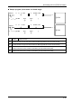

Creating Programs
4.4.3 Writing of Digital Data for Output (12-bit Mode)
The analog I/O unit (FP0R-A42/A21) writes data for conversion as the output switching flags
are not contained in the 12-bit mode.
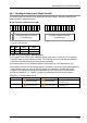
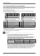
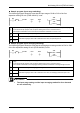
I/O allocation (12-bit mode)
WY3 WY2
CH1 data CH0 data
Writing data for conversion
• The analog I/O unit writes the analog output digital data of a maximum of 2 channels to two
memory areas (WY2/WY3) by user programs.
• Always insert a program which checks the upper and lower limits to make
written digital values be within the allowable data ranges referring the
programs described on the following pages.
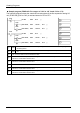
Mode Range setting Lower limit Upper limit
12-bit mode
± range -2000
2000
+ range 0
4000
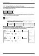
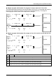
Sample program (12-bit mode: -10V to +10V range)
The following program shows the case that the data of DT0 to DT1 is converted and output to
the CH0 to CH1 of the first expansion analog I/O unit (FP0R-A42/A21).
<= K-2000 , DT0
R9010
[ F0 MV , DT0 , WY2 ]
1
>
1
>
>= K 2000 , DT0
①
④ ⑤
② ③
ⓐCH0
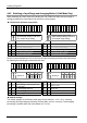
<= K-2000 , DT1
R9010
[ F0 MV , DT1 , WY3 ]
1
>
1
>
>= K 2000 , DT1
①
④ ⑤
② ③
ⓑCH1
4-28