
User manual


Compatibility with Conventional Models
7.2 Analog Output Unit
7.2.1 Compatibility with Conventional Models
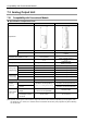
Specification Comparison Chart
Item FP0-A04V/ FP0-A04I FP0RDA4
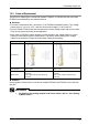
Appearance
DIP switch
None Equipped
Terminal block
1
2 (For voltage output / For current
output)
Resolution and Operation mode
12-bit (1/4000)
12-bit (1/4000)
14-bit (1/16000) (Note 1)
Number of channels
4 ch 4 ch
Analog output range
Voltage/Current (Each model)
Voltage/Current
(Built in one unit)
Analog output
voltage range
-10 to 10 V DC
Available (FP0-A04V) Available (Note 2)
-5 to5 V DC
Not available Available (Note 2)
0 to 10 V DC
Not available Available (Note 2)
0 to 5 V DC
Not available Available (Note 2)
Analog input
current range
0 to 20 mA
Not available Available (Note 2)
4 to 20 mA
Available (FP0-A04I) Available (Note 2)
Conversion speed
500 μs / channel 500 μs / All channels
Overall
precision
Voltage
±0.6%F.S. or less (at 25°C)
±1%F.S. or less (at 0 to 55°C)
±0.2%F.S. or less (at 25°C)
±0.4%F.S. or less (at 0 to 55°C)
Current
±0.3%F.S. or less (at 25°C)
±0.6%F.S. or less (at 0 to 55°C)
Power supply
(24V DC)
External power
supply
100 mA or less (FP0A04V)
130 mA or less (FP0A04I)
180 mA or less
Control unit
consumption current
increment
20 mA or less 10 mA or less
(Note 1):The resolution and operation mode is switched by the mode switch.
(Note 2):When selecting the 14-bit mode, the range can be set for each channel separately by user programs. Also,
the ranges of -5 to +5V DC, 0 to 10V DC and 0 to 20 mA DC can be set by user programs only when selecting
the 14-bit mode.
7-4