
User manual


7.3 Analog I/O Unit
(Note 2): When selecting the 14-bit mode, the range can be set for each channel separately by user programs. Also,
the ranges of -5 to 5 V DC and 0 to 10 V DC can be set by user programs only when selecting the 14-bit mode.
(Note 3): When selecting the 14-bit mode, the range can be set for each channel separately by user programs. Also,
the ranges of 0 to 10 V DC and 4 to 20 mA DC can be set by user programs only when selecting the 14-bit
mode.
(Note 4): When selecting the 14-bit mode, the averaging method can be set for each channel separately by user
programs. For details of the averaging methods, refer to the chapter 5 "Analog Input Averaging Processing".
7.3.2 Points of Replacement
The points for replacing the conventional model FP0A21 with the new model FP0RA21 as an
alternative are described below.
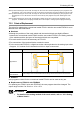
Hardware
• Although the positions of the mode switch and the terminal blocks are slightly different
between the conventional model FP0A21 and the new model FP0RA21, the setting methods
of the switches and the pin layout of the terminal blocks are compatible.
• The mode switch is set in the same way as FP0-A21.
• The connections of the terminal blocks are also the same.
• For the new model FP0RA21, a digital conversion value equivalent to the analog input value
of approx. 2 V is shown for the channels to which no input is connected.
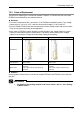
Item FP0A21 FP0RA21
Appearance
Mode switch
Terminal block
The settings of the mode switches and the wirings of the terminal blocks are the same.
Software
User programs created for the conventional model FP0A21 can be used as they are.
Replacement of FP0-A21 with FP0RA42
For replacing two FP0A21 units with FP0RA42, the user program should be changed. The
output range is either 0 to 20 mA or -10 to +10 V.
REFERENCE
• For details of the setting method of the mode switch, refer to “2.3.2 Setting
of Mode Switch“.
7-7