Model No. KV-S3065CL / KV-S3065CW These instructions contain information on operating the scanner. Before reading these instructions, please read the installation manual enclosed with this unit. Please carefully read these instructions, the enclosed installation manual and maintenance manual. Keep all documentation in a safe place for future reference. Keep the CD-ROM in the protective case. Do not expose the CD-ROM to direct sunlight or extreme heat and do not scratch or smudge the surface of the CD-ROM.
Thank you for purchasing a Panasonic “High Speed Color Scanner.” ≥ Panasonic supports your imaging needs with a reliable and easy to use document scanner. ≥ Panasonic has developed Panasonic Image Enhancement Technology to improve the quality of your scanned images even beyond the quality of your original document. ∫ System requirements When using the scanner, the required host computer conditions are as follows.
Table of Contents Page Notice . . . . . . . . . . . . . . . . . . . . . . . . . . . . . . . . . . . . . . . . . . . . . . . 4 Before You Start Precautions . . . . . . . . . . . . . . . . . . . . . . . . . . . . . . . . . . . . . . . . . . . 7 Component Identification . . . . . . . . . . . . . . . . . . . . . . . . . . . . . . 10 ≥ Power turn-on sequence . . . . . . . . . . . . . . . . . . . . . . . . . . . . . . . . . . . . . . . . 11 ≥ About LED . . . . . . . . . . . . . . . . . . . . . . . . . . . . .
Notice English WARNING: TO PREVENT FIRE OR SHOCK HAZARD, DO NOT EXPOSE THIS PRODUCT TO RAIN OR ANY TYPE OF MOISTURE. THE SOCKET-OUTLET MUST BE NEAR THIS EQUIPMENT AND MUST BE EASILY ACCESSIBLE. The product should be used only with a power cord that is supplied by the manufacturer. Power Source WARNING ≥ (220-240 V equipment) A certified power supply cord has to be used with this equipment. The relevant national installation and/or equipment regulations shall be considered.
Notice (For United Kingdom only) For your safety please read the following text carefully. This appliance is supplied with a moulded three pin mains plug for your safety and convenience. A 5 amp. fuse is fitted in this plug. Should the fuse need to be replaced, please ensure that the replacement fuse has a rating of 5 amps. and that it is approved by ASTA or BSI to BS1362. Check for the ASTA mark ASA or the BSI mark on the body of the fuse.
Notice Caution Labels 6
Precautions The following precautions are recommended to extend the life of the unit: Prior to scanning, remove all staples and paper clips from pages. Do not place any liquids near the unit. Do not place books, paper, or other items on the unit. —Accidental spillage of liquid into the unit may cause severe damage. If this occurs, turn the unit off, unplug the power cord and call for service. Do not place the unit in an area where there is a lot of smoke, dust, chemical fumes or vibration.
Precautions Operating Environment Do not place the unit in direct sunlight or in a cold draft. Hot Do not operate or place the unit in a vertical position. Cold Do not place the unit near a heating appliance or an air conditioning vent. Do not place the unit in a room with extremely high or low humidity. Do not place the unit near other appliances which generate large electrical noise. Do not place the unit on a carpet. (Static electricity can cause the unit to malfunction.
Precautions ∫ CD-ROM To prevent the CD-ROMs from accidental damages: Do not touch or write on the surface of the disc. Do not leave the disc out of its protective case. Do not place heavy objects on the disc case or drop the case. To clean the disc, hold the disc by its edges and wipe it from the center to the edges with a dry, soft cloth. Do not leave the disc in direct sunlight or near heat sources.
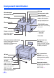
Component Identification Exit tray Exit substopper Exit document guide Exit extension tray Exit stopper Power indicator When the power is turned on, the green indicator lights. When an error occurs, the indicator will change to red, and light steadily or flash. Document guide STOP/START button Used to stop or start scanning a document. Hopper Hopper extension tray Power switch Front door release [ : on position ± : off position Inside the front door.
Component Identification ∫ Power turn-on sequence LED 1 Turn on the power of the scanner. 2 Turn on the power of the host computer after scanner’s LED stays green. ≥ The LED will now light. ≥ In case of the USB connection, the host computer recognizes the scanner automatically when the scanner is powered on even after the host computer is powered on.
Component Identification ∫ About the SCSI setting (Not required for USB connection) When connecting the scanner to a SCSI chain using a SCSI cable, perform the SCSI ID setting correctly. The scanner is provided with a DIP switch for the SCSI ID No. setting. DIP switch SCSI ID Setting Switch ID No.
Loading Documents Acceptable documents Document size: 48~297 mm (1.9~11.7 in.) 70~431 mm (2.75~17 in.) Paper thickness: Continuous paper feeding 40~157 g/m2 Single paper feeding 20~157 g/m2 Document smaller than A7 size 157 g/m2 (42 lbs.) only Maximum number of sheets loadable on the hopper tray: g/m2 40 52 64 75 80 90 104 157 lb.
Loading Documents ∫ When scanning multiple sheets Cautions: ≥ Please remove any staples from the document before scanning. ≥ Curled documents may cause a paper jam or damaging the unit, so please set the document flat before scanning. ≥ When scanning very important documents, confirm if the number of scanned images matches the number of actual pages. 1 Documents that have been stapled together or stacked together (as in a file folder) will need to be separated.
Loading Documents 4 Place the documents on the hopper with the side to be scanned facing up. Then push them in the direction of the arrow until they stop. Portrait A4, LTR Fill indicator (Limit mark) ≥ Be sure to place the documents on the B4TA3 hopper as shown in the diagram at the right. The amount of documents should not exceed the limit mark on the document guide. This may cause a paper jam or skew. ≥ The scanning document size is different for the KV-S3065CL and KV-S3065CW.
Loading Documents 6 When using long paper, pull out the hopper extension tray from the hopper Exit extension tray and the exit stopper from the exit extension tray. You can also extend the exit extension Exit stopper tray, if required. (See fig. 1) Hopper extension tray ≥ When scanning narrow documents as shown below, pull up the exit substopper. (See fig. 2) Fig. 1 Exit substopper Fig. 2 Scanning direction Document ≥ Thin paper document may curl and not be stacked correctly.
Paper Feed Settings ∫ Selecting the paper path for scanned document To select a U-turn path pass through to front, set the paper path selector to upper side. To select a straight path pass through to back, set the paper path selector to lower side. the the the the ≥ When scanning documents with a thickness of 0.2 mm to 1 mm, like folded documents, set the paper path selector to straight path. Paper path selector The paper path selector is located on the left side of the scanner.
Others ∫ How to use the control sheet and separation sheet x le 18 Documents B ≥ Use the same size control sheet as the scanning document. ≥ When printing the control sheet, if the pattern falls in the area from the top side of the document to 25 mm, adjust the printer. Also, copy the control sheet so that the pattern lies in the center of the copy. ≥ Be careful not to get the control sheet dirty. Do not fold or crease the control sheet. Scanning will not be performed properly.
Changing the Reference Plate Setting You can choose a background color to be scanned from white (black) to black (white). The scanner comes from factory set to black. The reference plate (B) and reference plate (F) setting must be changed simultaneously. ∫ Reference plate setting 1 2 Turn the power off. Use your hand to pull the front door release towards you (1). Then open the front door completely (2). Front door 2 2 1 Front door release (Inside the front door.
Changing the Reference Plate Setting 4 20 Close the front door. ≥ Push both sides of the front door down slowly until it clicks into place.
Clearing Paper Jams Torn documents, thin documents or documents that are creased on the top edge may cause paper jams. If a paper jam occurs, remove the jammed sheet according to the following procedure. ∫ Removing paper jams from the scanner Use your hand to pull the front door release towards you (1), open the front door (2) and pull the jammed document towards the front. Then close the front door. Front door 2 2 ≥ Push both sides of the front door down slowly until it clicks into place.
Cleaning the Unit ∫ Outside of the scanner ≥ Clean the unit at least once a month. 1 Turn the power off. 2 Clean the cover with a soft cloth. ≥ The document insertion and exit slots get dirty easily. Make sure to clean them. dirt and dust from the fan 3 Remove exhaust vent with a brush. Power switch ± : off position ∫ Inside the scanner ≥ Clean the unit at least once a week or when 20,000 sheets have been scanned, whichever comes first.
Cleaning the Unit ∫ Cleaning the rollers 1 Turn the power off. your hand to pull the front door 2 Use release towards you (1). Then open the front door completely (2). Front door 2 2 1 Front door release (Inside the front door.
Cleaning the Unit the roller cleaning paper 3 Use (KV-SS03) to remove the dirt from the surfaces of all rollers. ≥ When wiping off the dirt, hold the rollers to prevent them from rotating. Wipe the rollers all the way around from one end to the other in the directions of the arrows shown on the diagram to the right. ≥ Perform the retard roller cleaning only in the left direction. If cleaned in the right direction, the roller may slip out of the proper position.
Cleaning the Unit 4 Close the front door. ≥ Push both sides of the front door down slowly until it clicks into place. the roller cleaning counter with 5 Clear User Utility. ≥ Click [Clear Counter] button for [After Clean Roller] with User Utility. ∫ Cleaning the sensors, reflectors, double feed detectors and image sensor covers 1 Turn the power off. your hand to pull the front door 2 Use release towards you (1). Then open the front door completely (2).
Cleaning the Unit the image sensor cover with the 3 Clean roller cleaning paper. Then remove the dirt on the sensors, reflectors and double feed detectors with the included blower. Waiting sensor Skew sensor Starting sensor Skew sensor Image sensor cover (F) ≥ When cleaning the bottom image sensor cover, do not touch the tip of the plastic pointer (black) in the back of the unit. If the paper path selector is set to the lower side, it may cause an injury.
Replacing Consumables ∫ Replacing paper feed roller module 1 Turn the power off and unplug the power cord. Power switch ± : off position your hand to pull the front door 2 Use release towards you (1). Then open the front door completely (2). Front door 2 2 1 Front door release (Inside the front door.) your finger on the paper feed 3 Place roller block shaft and pull it towards you Paper feed roller block shaft to remove the paper feed roller block from the magnet.
Replacing Consumables the optional “Roller Exchange Kit 4 Open (KV-SS017)”, and take out the new paper feed roller module. the new paper feed roller 5 Install module with the gear on the left side and the bearings into the guide grooves of the side chassis in the scanner. (1) Then push up the green levers on both ends until they click into place. (2) ≥ Match the paper feed roller module with the bearings and guide grooves, and then attach it.
Replacing Consumables ∫ Replacing retard roller module open the conveyor towards you by 7 Pull using the indent on the right side. ≥ When the conveyor is pulled towards you, the click-stop mechanism will be released. Indent Caution: When opening the conveyor, be careful not get your finger stuck in the indent. Conveyor the right side of the shaft in the 8 Pull direction of the arrow and hold it there. (1) Pull the retard roller module in the direction of the arrow (2) and then remove it.
Replacing Consumables out the new retard roller module 9 Take in the optional “Roller Exchange Kit (KV-SS017)”. 10 Pull the right side of the shaft in the direction of the arrow and hold it there. (1) Attach the new retard roller module as shown in the diagram on the right (2) and then return the right side of the shaft in the direction of the arrow. (3) 1 Shaft Retard roller module ≥ Confirm if pin A and pin B are inserted in their notches correctly.
Replacing Consumables 11 Hold the conveyor using both hands, and close the conveyor by pushing it into the unit. ≥ When the conveyor is closed, the clickstop mechanism will operate. Caution: Indent If the conveyor is not closed correctly and the front door is closed, the conveyor may break. Conveyor 12 Close the front door. 13 Clear the roller replacing counter with User Utility. ≥ Push both sides of the front door down slowly until it clicks into place.
Shading Adjustment ¥ What is the purpose of the shading adjustment? The process whereby the variations in the distribution of the lamp’s light quantity are transformed into a fixed output within the scanning range is known as shading adjustment. It can be carried out by means of the User Utility using the special shading paper which is provided with this scanner.
Repacking Instructions It is highly recommended that you keep the original carton and ALL packing materials. If you need to transport or ship your scanner, please follow these instructions. ≥ Please use the original carton and all of the original packing materials. ≥ Improper repacking of the scanner may result in a service charge to repair the unit. ≥ The scanner should be handled in the correct (horizontal) position.
Specifications Model No. Item Scanner KV-S3065CL KV-S3065CW Scanning face Duplex scanning Scanning method Front side : CIS (Contact Type Color Image Sensor) Back side : CIS (Contact Type Color Image Sensor) Scanning width 227 mm (8.9 in.) Readout speed Simplex scanning : Approx. 65 sheets/min. (Letter, fed lengthwise, 200 dpi) Approx. 60 sheets/min. (A4, fed lengthwise, 200 dpi) Duplex scanning : Approx. 60 sheets/min. (Letter, fed lengthwise, 200 dpi) Approx. 55 sheets/min.
Specifications Model No.
Troubleshooting If a problem occurs while the unit is being used, check the following items and check the scanner status with the User Utility. If the unit still malfunctions, turn it OFF, unplug the power cord and call for service. Symptom Possible Cause The front door cannot be opened. The LED does not light when the power switch is turned ON. The computer does recognize the scanner. USB connection Scan speed is slow at USB connection. The document has been loaded on the hopper tray.
Troubleshooting Symptom Possible Cause Double feeding problems occurs frequently or the scanner stops loading while scanning. Remedy The rollers are dirty. Clean all of the rollers. (See page 23.) The rollers have reached their life expectancy. Replace the paper feed roller module and the retard roller module. (See page 27 and page 29.) The document is curled or folded. Flatten the document and load it again after reducing the pages. The irregular type document is to be scanned.
Index Page Page A F AC inlet . . . . . . . . . . . . . . . . . . . . . . . . . . . 10 Acceptable documents . . . . . . . . . . . . . . . 13 ADF / manual feed selector . . . . . . . . 10, 17 Fan exhaust vent . . . . . . . . . . . . . . . . 10, 22 Free rollers. . . . . . . . . . . . . . . . . . . . . . . . 24 Front door . . . . . . . . . 10, 19, 21, 23, 25, 27 Front door release . . . 10, 19, 21, 23, 25, 27 B G Belt . . . . . . . . . . . . . . . . . . . . . . . . . . . . . . 24 Blower. . . . . . . . .
Index Page Page O S Operating environment . . . . . . . . . . . . . . . 35 Option . . . . . . . . . . . . . . . . . . . . . . . . . . . . 35 OS. . . . . . . . . . . . . . . . . . . . . . . . . . . . . . . . 2 SCSI connection . . . . . . . . . . . . . . . . . . . . 2 SCSI connector . . . . . . . . . . . . . . . . . . . . 10 SCSI ID setting . . . . . . . . . . . . . . . . . . . . 12 Separation roller. . . . . . . . . . . . . . . . . . . . 24 Separation sheet . . . . . . . . . . . . . . . . . . .
Panasonic Digital Document Company A Unit of Matsushita Electric Corporation of America Two Panasonic Way, Secaucus, New Jersey 07094 Panasonic Canada Inc. 5770 Ambler Drive, Mississauga, Ontario, L4W 2T3 Matsushita Electric Industrial Co., Ltd. http://www.panasonic.co.jp/global/ © 2004 Panasonic Communications Co., Ltd. All Rights Reserved.