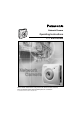
Network Camera Operating Instructions Model No. KX-HCM8 Please read this manual before using and save this manual for future reference. Panasonic Network Camera Site: http://www.panasonic.
Operating Instructions Introduction Thank you for purchasing a Panasonic Network Camera. Check the following items when unpacking. Network Camera — 1 pc. Operating Instructions — 1 pc. Getting Started — 1 pc. AC Adaptor — 1 pc. Flexible Stand — 1 pc. Screws — 3 pcs. Setup CD-ROM — 1 pc. Rear Mounting Adaptor — 1 pc. For operation assistance: 2 • Call 1-800-272-7033 • Refer to the Panasonic Network Camera Site http://www.panasonic.
Operating Instructions Trademarks • Netscape and Netscape Navigator are either registered trademarks or trademarks of Netscape Communications Corporation in the U.S. and other countries. • Adobe and Acrobat are either registered trademarks or trademarks of Adobe Systems Incorporated in the United States and/or other countries. • Ethernet is either a registered trademark or a trademark of Xerox Corporation in the United States and/or other countries.
Operating Instructions IMPORTANT SAFETY INSTRUCTIONS When using this unit, basic safety precautions should always be followed to reduce the risk of fire, electric shock, or personal injury. 1. 2. 3. 4. 5. Read and understand all instructions. 6. Do not install near any heat sources such as radiators, heat registers, stoves, or other devices (including amplifiers) that produce heat. 7.
Operating Instructions Table of Contents 1 Product Introduction...................................................... 7 1.1 Getting to Know Network Camera .................................................... 8 1.1.1 Main Features............................................................................................. 8 1.1.2 System Requirements .............................................................................. 10 1.1.3 Authentication—System Security Feature ...............................
Operating Instructions 3.5.6 3.5.7 3.5.8 3.5.9 3.5.10 3.5.11 3.5.12 3.5.13 3.5.14 3.5.15 4 4.1 4.2 4.3 4.4 5 5.1 5.2 5.3 5.4 5.5 5.6 Top View Image ........................................................................................60 Image Transfer..........................................................................................62 Camera Setup ...........................................................................................74 Multi-Camera...........................................
Operating Instructions Section 1 Product Introduction [For assistance, please call: 1-800-272-7033] 7
Operating Instructions 1.1 1.1.1 Getting to Know Network Camera Main Features Easy installation Setup CD-ROM simplifies the installation. Insert the Setup CD-ROM and autorun program should start the application automatically. This program automatically finds Network Camera on the network. High-Speed Motion JPEG Network Camera has an integrated web server. Motion JPEG displays up to 15 frames per second, if the network provides enough bandwidth.
Operating Instructions Update Firmware If new firmware is released, you can download the latest program from Network Camera Technical Support Site. Installation is easy and fast. Refer to page 82 for details. Authentication Authentication window requires you to enter the administrator/general user ID and password. Password security can prevent unregistered users/intruders from accessing your image from their web browsers. Refer to Section 1.1.3 Authentication—System Security Feature for details.
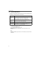
Operating Instructions 1.1.2 System Requirements The PC (Personal Computer) and the network must meet the following technical specifications for Network Camera to work properly. Item Operating System Description Microsoft® Windows® 95, Microsoft Windows 98/SE Microsoft Windows 2000, Microsoft Windows Me Microsoft Windows NT® 4.0, Microsoft Windows XP Network Protocol TCP/IP network protocol installed.
Operating Instructions 1.1.3 Authentication—System Security Feature Authentication window requires you to enter the administrator/general user ID and password for security. Password security can prevent unregistered users/ intruders from accessing your image from their web browsers. Authentication windows are not displayed in the default. Refer to page 56 for setting up Authentication window, the administrator ID and the password. Refer to page 58 for setting up the general user ID and the password.
Operating Instructions 1.2 Included Accessories The following items are provided with Network Camera. Additional pieces can be ordered by calling 1-800-332-5368. AC Adaptor — 1 pc. Flexible Stand — 1 pc. Order No. PQLV10Y Order No. PSKL1020Z Screws — 3 pcs. Setup CD-ROM — 1 pc. Order No. PQHE5004Z Order No. PSQX2904ZCD Order No. PSYLHCM8M Rear Mounting Adaptor — 1 pc. Notes 12 • If any items are missing, contact the dealer immediately.
Operating Instructions Setup CD-ROM The setup program simplifies Network Camera installation. Adobe® Acrobat® Reader 4.05 or later enables you to see the Operating Instructions on the Setup CD-ROM. If Adobe Acrobat Reader is not installed on the PC, double-click "ar405eng.exe". Refer to "ReadmeEng.txt" for the directory and file structure of the Setup CD-ROM. Notes • Do not scratch, smudge, write or label either surfaces of the Setup CDROM. Setup CD-ROM may have a scratch on the surface.
Operating Instructions 1.3 Camera Feature Locations 1.3.1 Front View Power Indicator (Refer to page 79 for the setup.) Fixed Focus Lens 1 m (40 inches) – Infinity Attachment Lens (30.5 mm) (customer provided) Turn the attachment lens till it stops. Power Indicator Power Indicator can be controlled on Indicator Control window on page 79. Power Indicator blinks in the following situations. • During the Update Firmware. • During initializing after pushing CLEAR SETTING button.
Operating Instructions 1.3.2 Rear View I/O Connector (Refer to page 91.) CLEAR SETTING button (Refer to page 97.) Ethernet port (RJ-45) (Refer to page 20.) MAC Address and Serial Number are indicated on the label. Record both of them on Network Camera Memo on page 3. They are indispensable for setting network parameters after mounting Network Camera and for future customer servicing. (Refer to page 29.) DC IN jack (Refer to page 20.) Ethernet Indicator (Refer to page 20.
Operating Instructions Section 2 Network Camera Setup 16
Operating Instructions 2.1 Installation Procedure Select the Network Camera configuration type. (Page 18—Page 19) Connect Network Camera for installation. (Page 20) Prepare the network parameters for Network Camera. (Page 21—Page 22) Check the proxy server setting. (Page 26—Page 27) Set up Network Camera with Setup CD-ROM. (Page 28—Page 31) Confirm the Network Camera Access from the Internet. (Page 32—Page 33) Mount Network Camera.
Operating Instructions 2.2 Network Camera Configuration Type Network Camera can be connected over the LAN/Intranet and the Internet. Select from the four Network Camera configuration types. Network parameters differ depending on the Network Camera configuration type. [Type 1]—LAN/Intranet Connection with an Ethernet Switching Hub Network Camera can be installed on the LAN/Intranet. Ethernet switching hub*1 LAN/Intranet *1 Network traffic can be improved by using the Ethernet switching hub.
Operating Instructions [Type 3]—Internet Direct Connection with a Modem Network Camera can be installed alone without PC on the network. When you set up Network Camera in [Type 3], connect Network Camera temporarily in [Type 1], [Type 2] or [Type 4]. Modem Internet Note Some xDSL services use PPPoE. Network Camera does not support PPPoE. If the Internet connection requires PPPoE, connect with the broadband router supporting PPPoE like [Type 2].
Operating Instructions 2.3 How to turn on Network Camera for Installation Connect the DC plug of the AC adaptor to the DC IN jack and a category 5 straight/ cross cable to the Ethernet port. Connect the AC plug of the AC adaptor to the power outlet to turn on Network Camera. Ethernet Indicator turns on when the network is active. Thread the AC adaptor line through the hook downward. AC adaptor Power Outlet DC plug Connect a category 5 cable to the Ethernet port.
Operating Instructions 2.4 Network Parameters 2.4.1 Preparing the Network Parameters for Network Camera Before starting to set up the network parameters of Network Camera, make note of corresponding network parameters. [Type 1] Ask your network administrator for the network parameters. [Type 2] Refer to the broadband router’s manual for the network parameters. [Type 3] Ask your ISP (Internet Service Provider) for the network parameters. [Type 4] Install Network Camera in the default condition.
Operating Instructions Network Parameters Table Parameters Port No. Network Camera Configuration Type [Type 1] 80 (default) IP address Check [Static], and set the static private IP address. [Type 2] [Type 3] 1 2 80 (default) ** Check [Static], and set the static private IP address.*3 80 (default)* Set the Subnet Mask fitted to your network. Default Gateway Set Default Gateway address. Set the private Set Default IP address of the Gateway broadband router address.
Operating Instructions How to refer the network parameters from the PC If you cannot get the network parameters, you can refer to the network parameters except for IP address from the PC on the same network in the following procedure. • When using Windows 95, Windows 98 or Windows Me 1. Click [Start] –> [Run...]. Run window appears. These steps are slightly different depending on the operating system. 2. 3. Enter "winipcfg" and click [OK]. IP configuration window appears. 4.
Operating Instructions 2.4.2 Setting IP Address of the PC in [Type 4] Configuration Type Your PC needs to have a static private IP address to access Network Camera in [Type 4] configuration. 1. Follow the steps below, appropriate for your operating system to open TCP/IP Properties window on the PC.
Operating Instructions 2. TCP IP Properties window appears. Set "192.168.0.250" in the IP address data field and "255.255.255.0" in the Subnet Mask data field. 3. Click [OK]. Private IP address Private IP address is the network ID that is not used on the Internet. They are classified into Class A, Class B and Class C, as shown in the next table. Set the IP address in the range of the number specified in the class meeting to your local network scale.
Operating Instructions 2.5 Proxy Server Setting A proxy server may prevent you from connecting directly to Network Camera in some corporate environments. The web browser can set up the IP address communication without using a proxy server. Consult your ISP or network administrator. Note A proxy server is generally used to maintain security on a network that offers an Internet connection.
Operating Instructions 3. Enter the IP address of Network Camera assigned from your ISP or network administrator into the Do not use proxy server for addresses beginning with data field. 4. Click [OK] on all of the opening windows.
Operating Instructions 2.6 Simple Installation using the Setup CD-ROM After finishing cabling, turn on Network Camera and insert the Setup CD-ROM in the CD-ROM drive of the PC. Setup CD-ROM should start the application automatically. This program automatically finds Network Cameras on the network. 1. 2. 28 Turn on Network Camera. Insert the Setup CD-ROM in the CD-ROM drive of the PC. (If Network Camera Setup window does not appear, click "setup.exe" on the Setup CD-ROM.
Operating Instructions 3. Click [Network Configuration]. Network Camera List window appears. Setup program finds all Network Cameras connected on your local network. It lists all of MAC addresses and IP addresses of Network Cameras. Network Cameras that are isolated by the use of a home gateway or broadband router will not be detected. Record MAC address on the Network Camera Memo on page 3. It is useful for customer servicing.
Operating Instructions 4. Select your target Network Camera from the list as shown in example (A) on Network Camera List window on page 29 and click [Select]. Configuration window appears. Refer to page 21 and page 22 and enter the correct network parameters. Refer to page 51 for details of each parameter. 5. Click [Save] when finished. The "Successful!" message box appears. Notes 30 • Network Camera automatically restarts after saving the network configuration.
Operating Instructions 6. Click [OK]. Refer to page 50 for Setup Page (Network window). 7. Click [Top Page]. Top Page appears. Click the language to change the display. Refer to page 37 for Top Page. Notes • When viewing images for the first time in the Internet Explorer, a pop-up Security Warning window may appear. The window requests your permission to download ActiveX® Controls (OCX file) used to display Motion JPEG. Refer to page 39.
Operating Instructions 2.7 Network Camera Access from the Internet [Type 2] and [Type 3] of the Network Camera configuration type allow Network Camera to be accessed from the Internet. Port Forwarding (IP Masquerade) feature Set up the Port Forwarding feature to the broadband router if the [Type 2]— Internet Connection with the Broadband Router on page 18 is configured. Port Forwarding feature translates a global IP address to a private IP address and assign a unique port number for each Network Camera.
Operating Instructions Top Page Click the language to change the display. Refer to page 37 for Top Page. Note When viewing images for the first time in the Internet Explorer, a pop-up Security Warning window may appear. The window requests your permission to download ActiveX Controls (OCX file) used to display Motion JPEG. Refer to page 39. If Top Page does not appear Confirm the network parameters and the connections of Network Camera through page 18—page 32.
Operating Instructions 34
Operating Instructions Section 3 Network Camera Screen and Setup Window [For assistance, please call: 1-800-272-7033] 35
Operating Instructions 3.1 Network Camera Flow Chart Top Page enables you to access Top View Image screen (Single Camera/MultiCamera screen). Authentication window can set password for the link at (A). Enter "http://IP Address (or URL):Port No." on the web browser. When port number is 80 (default), you do not need to enter port number. (A) Top View Image screen Single Camera screen Top Page Multi-Camera screen Click the language to change the display.
Operating Instructions 3.2 Top Page Top Page allows you to select the Single/Multi-Camera screen in Motion JPEG or JPEG - Regularly Refresh. Motion JPEG enables you to view the image like a motion video, and JPEG - Regularly Refresh can be set the refresh interval. Enter "http://IP Address (or URL):Port No." on the web browser. When port number is 80 (default), you do not need to enter port number. Then Top Page appears. Example • Accessing Top Page using port number 80 (default) http://192.168.0.
Operating Instructions Notes • If a port number is specified in the IP address, "http://" must precede the IP address, otherwise the port number will not be recognized. • When viewing images for the first time in the Internet Explorer, a popup Security Warning window may appear. The window requests your permission to download ActiveX Controls (OCX file) used to display Motion JPEG. Refer to page 39. Motion JPEG The image refreshes continuously like a motion video.
Operating Instructions ActiveX Controls When viewing images for the first time in the Internet Explorer, a pop-up Security Warning window may appear. The window requests your permission to download ActiveX Controls (OCX file) used to display Motion JPEG. Allow the file to be installed. It is required and will not cause any problems with other applications on the PC. If Security Warning window appears, click [Yes].
Operating Instructions 3.3 Single Camera Screen Single Camera screen has an Operation Bar on the left. It can change the image resolution, the image quality and image size. [Viewer] links to the Buffered Image screen. Image field (Displaying of Single Camera image) Operation bar Notes 40 • The Screen Saver can prevent the PC monitor from burning in displaying the same image. • Selecting a resolution of 640 x 480 will result in a slight loss of speed when viewing Motion JPEG.
Operating Instructions 3.3.1 Using Operation Bar Operation bar controls the general use of Network Camera. The following sections describe the general way of using it. (1) (2) (3) (1) Locked Display: Brightness Control can be locked. Locked appears when the operation bar is clicked. (2) Brightness: Brightness control has nine steps including [STD] (Standard). Clicking [-] and [+] buttons changes the brightness of image. Brightness can be locked on Camera Setup window on page 74.
Operating Instructions 3.3.2 Viewing Buffered Image Screen Buffered Image screen can be viewed by clicking [Viewer] on the operation bar. Buffered Image is saved in the internal memory of Network Camera by clicking [Start Capture]. Alarm/Timer mode in the Image Transfer on page 62 can also buffer the image. Buffered Image is erased by power off, restarting, Update Firmware, resetting to Factory Default and when Image Transfer or Name/Time window is saved and clicking [Start Capture].
Operating Instructions [Start Capture] : [Start Capture] saves the individual images to the internal memory. Network traffic, PC performance, image quality and image resolution influence [Play] mode time and the refresh interval of the image. The resolution is the same as the current image settings. At a resolution of 320 x 240 in standard, Network Camera stores approximately 80 frames. [Viewer] : [Viewer] enables you to view the buffered image by clicking [Start Capture].
Operating Instructions 3.4 Multi-Camera Screen Four separate Network Camera images can be displayed in both Motion JPEG and JPEG - Regularly Refresh. You can jump to each individual Network Camera by clicking Camera Name. Refer to page 76 for how to configure each Network Camera. Link to each Single Camera when clicking Camera Name. Image Field (Displaying MultiCamera Image) Changes the image size. Notes 44 • On the Multi-Camera screen, the maximum image resolution is limited to 320 x 240.
Operating Instructions 3.5 Setup Page Setup Page controls all features of Network Camera. Authentication window protects the Network Camera security. It enables only administrator to access Setup Page by entering ID and Password. Enter "http://IP Address (or URL) :Port No./config.html" on the web browser and press [Enter]. When port number is 80 (default), you do not need to enter port number. Then Setup Page appears. Example • Accessing Setup Page using port number 80 (default) http://192.168.0.
Operating Instructions Setup Page (1) (2) (3) (4) (5) (6) Version number (7) (8) (9) (10) (11) (12) (13) (14) (15) (16) Note Firmware Version number indicated on Setup Page is important for your future support of Network Camera.
Operating Instructions Item Description (1) Go to Top Page Links to Top Page. You can access Single/MultiCamera screen in Motion JPEG/JPEG - Regularly Refresh. Refer to page 49. (2) Network Configures the network setting (Static/DHCP, Default Gateway, Port Number, DNS, DDNS and Bandwidth). Refer to page 50. (3) Name/Time Sets the Camera Name on the Single Camera screen.
Operating Instructions Item (10) External Output Control Description Sets the External Device Control Output setting to attach external sensors/devices. (Open or Short to GND) Refer to page 78 and page 91. (11) Indicator Control Sets Power Indicator operation. Indicator will be turned on in the default. Refer to page 79. (12) Status Displays general information of Network Camera. Refer to page 80. (13) Restart Restarts Network Camera retaining any settings you entered.
Operating Instructions 3.5.1 Go to Top Page Click [Go to Top Page] on Setup Page. You can access the Single Camera and Multi-Camera screen in Motion JPEG/JPEG - Regularly Refresh. Click the language to change the display.
Operating Instructions 3.5.2 Network Network window configures network parameters. Restart Network Camera to make the parameters effective. 50 • You can set disable Configuration window from the Setup CD-ROM for the security by clearing the check. 1. Click [Network] on Setup Page.
Operating Instructions 2. Enter each parameter in the proper data field. Click [Save] when finished. • 3. Click [Cancel] to quit the current settings. The window returns to Setup Page without saving the parameters. Click [Restart Now!] to restart to make the changed parameters effective. Instructions for the data fields Port No. • You can set up the port number of Network Camera. (Default is 80.
Operating Instructions Instructions for the data fields Static • IP Address • Subnet Mask DHCP • • Check [Static], when having specified IP address assigned to Network Camera from your ISP or administrator. Enter the specified IP address and Subnet Mask. • If you use Network Camera on the LAN, set up in the same class as your PC is in. Refer to page 25 for the class. • Refer to page 93 for the IP addressing.
Operating Instructions Instructions for the data fields DDNS • Your E-mail Address • Personal (Camera) URL • Your Account Link Max. Bandwidth Usage • If your ISP specified IP address of Cable/xDSL modem is not static, you need to contract to DDNS (Dynamic Domain Name System) service. Check DDNS Enable, enter Your E-Mail Address and refer to an attached leaflet for DDNS service. • By enabling DDNS service viewnetcam.com, you can create a personalized web address (for example, bob.viewnetcam.
Operating Instructions 3.5.3 Name/Time Name/Time window is used to assign a name to each Network Camera. Date and Time entered on Name/Time window are used for the Alarm/Timer mode in the Image Transfer feature and on the Buffered Image screen. NTP automatically adjusts the internal clock of Network Camera. 1. Click [Name/Time] on Setup Page. 2. Enter the Camera Name and Date and Time. Click [Save] when finished. • Click [Cancel] to quit the current settings.
Operating Instructions Instructions for the data fields Date and Time • Time stamp on the Buffered Image screen can be changed [AM/PM] or [24H]. • Only 24 h time mode is used in the Alarm/Timer mode in the Image Transfer feature. Auto NTP (Network Time Protocol) Server synchronizes Network Adjustment Camera internal clock. It adjusts automatically everyday. Check the box to enable NTP. • NTP Server Address or Host Name Ask your ISP or the network administrator for the NTP Server.
Operating Instructions 3.5.4 Security: Administrator Security: Administrator window allows the administrator to limit or exclude access to the selected Network Camera. Individual levels of access can be defined for multiple users. Notes 56 • If Network Camera is to be accessed via the Internet, use authentication window for security. It will prevent any unauthorized person from changing your Network Camera parameters. • Refer to page 57 for details about authentication security. 1.
Operating Instructions Instructions for the data fields Authentication Authentication window can be set in the three patterns. Enable None: No authentication window appears. Anyone can access all screens (Single Camera/Multi-Camera screen) and pages (Top Page and Setup Page). Administrator only: Authentication window appears when accessing Setup Page. Authentication window does not appear when accessing Top Page.
Operating Instructions 3.5.5 Security: General User Security: General User window allows the administrator to create the general user ID and password for the security level defined as general user. Up to 30 individual user names can be defined. The various security levels are explained on page 57. 58 1. Click [Security: General User] on Setup Page. 2. Enter each parameter in the proper data field. Click [Save] when finished. • Click [Cancel] to leave the current settings unchanged.
Operating Instructions Instructions for the data fields General User Authentication The General User can be up to 30. Each of them can have their own ID and password. (1) User ID List • User ID List displays the registered user name. • [Delete] and [Modify] deletes/modifies the general user in the list. Select the desired user and click [Delete] or [Modify]. (2) New User Enter the general user ID, password and reenter the password to confirm.
Operating Instructions 3.5.6 Top View Image Top View Image Setting window can change settings for Top Page, Single Camera and Multi-Camera screen such as the initial language, the image resolution, image quality, refresh interval as the initial setting, Limit time of Continuous Motion JPEG and On the Air time. 1. Click [Top View Image] on Setup Page. 2. Select the each parameter. Click [Save] when finished. • Click [Cancel] to quit the current settings.
Operating Instructions Instructions for the data fields Top Page • • Top Page title can be changed. Enter the new title. • Refer to unavailable character set 1 on page 93 but [space] is available. • Refer to displayable character set on page 94. Network Camera picture on Top Page can be changed. Enter the URL (http://) to display the picture on the specified web site. • • Network Camera picture on Top Page can be set the link to the specified web site. Enter the URL (http://).
Operating Instructions 3.5.7 Image Transfer Image Transfer window can set the Image Transfer feature. Network Camera can buffer images and send the images via e-mail or FTP. The request to send the image is initiated by a contact closure from the external sensors/devices connected to the External I/O using the Alarm mode. The external sensors/ devices are customer provided. The images can also be sent in the interval of time using the Timer mode. Make sure Date and Time has been configured.
Operating Instructions Non Transfer mode Non Transfer mode enables [Start Capture] on the operation bar to buffer the image on the Single Camera screen. Refer to page 42. Capture Control can lock [Start Capture] on the operation bar to prevent the user from capturing the Buffered Image. Click [Clear Buffered images] to clear the buffered image. [Clear Buffered images] does not save the parameters. 1. Click [Image Transfer] on Setup Page. 2. Select the each parameter. Click [Save] when finished.
Operating Instructions Transfer in the Alarm Mode The Alarm mode can transfer an image via e-mail or FTP when the alarm trigger is active. To activate the alarm trigger, the External Sensor Input of External I/O must be connected with the external sensors/devices. The Alarm mode can send the e-mail without transferring the image. The Alarm mode uses the Network Camera internal clock. Make sure Date and Time has been configured. Refer to page 54 about Date and Time. 1.
Operating Instructions Instructions for the data fields a. External Sensor Input of External I/O activates the alarm trigger. Refer to page 91. b. Active Time of Trigger The active trigger time can be set in the primary time and the secondary time. The secondary time is the supplement of the primary time. Always: always activates the alarm trigger. Operational between: Sets the start and stop time of the primary time. The day of the week can be set by checking.
Operating Instructions a. b. c. a. 66 Selects Transfer Method. Non Transfer without Memory Over Write: Image buffering will stop when the internal memory is full. Non Transfer with Memory Over Write: Buffered image will overwrite the older image data when the internal memory is full. FTP: Enters the server address*1 or Host Name*2, Port Number (1— 65535), Login ID*2 and password*2 to access the FTP server and upload file name*2 including full path.
Operating Instructions Over write setting: Selects [Over Write...] to overwrite the transferred image or [Add time...] to save each transferred image. Data transfer method: Use [Passive Mode] normally. If FTP does not work properly, ask your ISP or network administrator about the transferring mode of FTP server. [Passive Mode] or [Active Mode] is available. b. Mail: Sets the SMTP and POP3 server address* 1 or Host Name*2, Login ID* and Password* . From (Reply)*3: Enter the e-mail address of [Reply-to].
Operating Instructions Setting Example a. b. c. d. e. f.
Operating Instructions Setting explanation a. The active time of trigger is set between 9:00 AM to 6:00 PM from Monday to Friday. When the alarm occurs in the setting time, the images are transferred to FTP server, and the notification is sent to the specified user via email. The alarm trigger is on when the sensor signal is changed to the [Rising] (GND to Open High) of External Sensor Input of External I/O. b. The secondary time is set inactive. c.
Operating Instructions Transfer in the Timer Mode The timer mode can be activated by entering the active time, the image setting, frequency setting and the transfer method on Image Transfer window. Buffered Image can also be transferred via e-mail or FTP. The timer mode uses the Network Camera internal clock. Make sure Date and Time has been configured. Refer to page 54 about Date and Time. 1. Click [Timer] on Image Transfer window. a. b. c. d. e.
Operating Instructions Instructions for the data fields a. Buffers or transfers by the timer trigger. b. Active Time of Trigger Always: always activates the timer trigger. The timer trigger interval can be set in e. Image Buffer Frequency Setting. Operational between: Sets the start and stop time of the primary time. The day of the week can be set by checking. If the setting time passes over midnight, check the check box of only the day of start time. Start and stop time is set only in 24 h time mode.
Operating Instructions a. b. a. 72 Selects Transfer Method. Non Transfer without Memory Over Write: Image buffering will stop when the internal memory is full. Non Transfer with Memory Over Write: Buffered image will overwrite the older image data when the internal memory is full. [Primary] or [Secondary] on the operation bar can be displayed to view the Buffered Image screen in Non Transfer setting.
Operating Instructions Over write setting: Selects [Over Write...] to overwrite the transferred image or [Add time...] to save each transferred image. Data transfer method: Use [Passive Mode] normally. If FTP does not work properly, ask your ISP or network administrator about the transferring mode of FTP server. [Passive Mode] or [Active Mode] is available. b. Mail: Sets the SMTP and POP3 server address* 1 or Host Name*2, Login ID* and Password* . From (Reply)*3: Enter the e-mail address of [Reply-to].
Operating Instructions 3.5.8 Camera Setup Camera Setup window sets White Balance and Power Line Frequency. You can lock the Brightness feature. 1. Click [Camera Setup] on Setup Page. 2. Select the each parameter in the proper data field. Click [Save] when finished. • 74 Click [Cancel] to quit the current settings. The window returns to the Setup Page without saving the parameters.
Operating Instructions Instructions for the data fields White Balance Auto (default) — Auto White Balance Fixed Indoor — Color Temperature: 2800K, Electric Bulb Fixed Fluorescent_1 Color Temperature: — 3600K, Natural fluorescent light Fixed Fluorescent_2 Color Temperature: — 4000K, Natural fluorescent light Fixed Outdoor — Color Temperature: 6000K, Solar light Hold — Holds the current White Balance Notes • Power Line Frequency The wrong White Balance setting will cause Network Camera to displ
Operating Instructions 3.5.9 Multi-Camera Multi-Camera window enables the setting of Multi-Camera screen. Camera Name and IP address of each Network Camera must be entered to view the MultiCamera screen. Registering IP addresses of the other Network Camera enables you to view on the Multi-Camera screen. Clicking Camera Name of Network Camera on the Multi-Camera screen accesses the Single Camera screen to control the image. First Network Camera is named on Name/Time window on page 54.
Operating Instructions 2. Select/Enter the each parameter. Click [Save] when finished. • Click [Cancel] to quit the current settings. The window returns to Setup Page without saving the parameters. Instructions for the data fields Enable check box The checked camera image can be seen on the MultiCamera screen. IP Address (or URL)*1 or Host Name*2 Enter the desired IP address of Network Camera or Host Name and Port Number. (You do not need to enter port number 80 [default].
Operating Instructions 3.5.10 External Output Control External Output Control window enables the External Device Control Output signal to activate the external sensors/devices. (Open or Short to GND) The network administrator should set up this setting. Note Refer to page 91 for Interfacing to the External I/O. 1. Click [External Output Control] on Setup Page. 2. Check [Open] means the External Device Control Output becomes high impedance (open collector).
Operating Instructions 3.5.11 Indicator Control Indicator Control window allows you to select Power Indicator operation. Power Indicator operation has three patterns. • Always on • Turns on when accessing Network Camera • Always off Notes • Power Indicator can be controlled in case the administrator does not want to draw attention to Network Camera. This may be desirable when used for security applications. • Indicator Control window cannot control Ethernet Indicator on page 15. 1.
Operating Instructions 3.5.12 Status Status displays general information about Network Camera. Note When some trouble occurs, the information is useful.
Operating Instructions 3.5.13 Restart Restart window restarts Network Camera with the parameters saved. Restarting is required when the network parameters are changed. 1. Click [Restart] on Setup Page. 2. Click [Restart Now!]. • Click [Cancel] to quit. The window returns to Setup Page.
Operating Instructions 3.5.14 Update Firmware Update Firmware window allows the user to install the latest version of the Network Camera internal operating system. In most cases, this will never be necessary. Changes may be necessary to accommodate new operating systems or new web browsers that are not shown on page 10. In those cases, Update Firmware would be available from the Network Camera Technical Support Site at http://panasonic.co.jp/pcc/en/.
Operating Instructions 4. Click [Update Firmware] on Setup Page. 5. Click [Update Firmware]. Wait about one minute. Note If you click [Update Firmware], operation cannot be canceled. If canceled, refer to page 108.
Operating Instructions 6. Click [Browse...] to select the firmware from the file selector. 7. Select a desired Firmware file (including the path information) and click [Open]. 8. Make sure the desired firmware file name is selected correctly, and click [Update Firmware]. • A dialog box appears to choose the file. Restarting window is displayed, and Network Camera restarts automatically. Restart operation takes about one minute.
Operating Instructions 3.5.15 Reset to Factory Default Reset to Factory Default window initializes all the parameters including the ID, Password, IP address and Subnet Mask except Date and Time setting to the factory default. Reconfirm the settings before doing the Reset to Factory Default operation. 1. Click [Reset to Factory Default] on Setup Page. 2. Click [Execute]. • Click [Cancel] to quit. The window returns to Setup Page. Notes • Do not turn off the power during the Reset to Factory Default.
Operating Instructions Section 4 Technical Guides 86
Operating Instructions 4.1 Mounting Four mounting methods are shown in the following figures. Confirm the top and bottom of Network Camera when mounting. Note Mounting and cabling instructions described in this Operating Instructions follow generally accepted guidelines suitable for residential installations. In some areas, commercial and industrial installations are regulated by local or state ordinances.
Operating Instructions Wall Mounting 1) Mount the Flexible Stand firmly to the wall or the beam using the three screws. 2) Attach Network Camera by screwing the threaded mount into the tripod mounting hole. 3) Adjust the position of Network Camera and secure the Flexible Stand. Do not over tighten. 1) 2) 3) Note Rear Mounting Adaptor can be used in wall mounting. Refer to page 89 for Rear Mounting Adaptor.
Operating Instructions Ceiling Mounting 1) Mount the Flexible Stand firmly to the ceiling or the beam using the three screws. 2) Attach the Rear Mounting Adaptor to the rear of Network Camera. 3) Attach Network Camera by screwing the threaded mount into the tripod mounting hole. 4) Adjust the position of Network Camera and secure the Flexible Stand. Do not over tighten.
Operating Instructions Notes • Make sure the Power Indicator is always in the upper right corner when you mount. • The upside down mounting may cause Network Camera to fall down. Power Indicator On the Stand On the wall On the ceiling top top bottom bottom bottom top bottom CAUTION Network Camera is intended for indoor use only. Prolonged exposure to direct sunlight or halogen light may damage the CMOS sensor.
Operating Instructions 4.2 Interfacing to the External I/O The Alarm mode in the Image Transfer feature requires the external sensors/ devices to be connected to the External Sensor Input of the External I/O. Certain features of this Network Camera can be activated by an external sensor that senses physical changes in the area Network Camera is monitoring. These changes can include motion detection or a physical change in the monitored area.
Operating Instructions Circuit Diagram Example Relay Light Network Camera 4 8 12 VDC 3 2 1 Door Sensor CAUTION 92 • THE EXTERNAL I/O IS NOT CAPABLE OF CONNECTING DIRECTLY TO DEVICES THAT REQUIRE LARGE AMOUNTS OF CURRENT. IN SOME CASES, A CUSTOM INTERFACE CIRCUIT (CUSTOMER PROVIDED) MAY HAVE TO BE USED. SERIOUS DAMAGE TO NETWORK CAMERA MAY RESULT IF A DEVICE IS CONNECTED TO THE EXTERNAL I/O THAT EXCEEDS ITS ELECTRICAL CAPABILITY.
Operating Instructions 4.3 ASCII and ISO-8859-1 Character Table The characters of the ASCII character table are available for use in the various setup windows. IP addressing (Assignment of the IP address) Address consists of one to four numbers (0—255). By far most common form is four decimal numbers, (e.g., 192.168.0.253). ("0.0.0.0" and "255.255.255.255" are not available.) Unavailable character set 1 [Space], ["], ['], [#], [&], [%], [=], [+], [?], [<], [>] and [:] are not available.
Operating Instructions Displayable character set Network Camera can display ISO-8859-1 character set for West European languages and the Shift-JIS character set for Japanese. Network Camera screen may display the unreadable characters if the operating system or the entered character set is different from the language selected on Top View Image Setting window.
Operating Instructions 4.4 Maintenance To keep Network Camera functioning in good condition, maintenance plays an important part. Keep maintenance when using Network Camera. After removing dust from the Fixed Focus Lens, wipe the Fixed Focus Lens with lens cleaning paper. Fixed Focus Lens • Do not forcedly move the lens part around the Fixed Focus Lens. Touching it may damage the Pan/Tilt motor. • Do not touch the Fixed Focus Lens.
Operating Instructions Section 5 Specification and Troubleshooting 96
Operating Instructions 5.1 Network Camera Reset Procedure—Default Settings If the user forgets settings or passwords, Network Camera can be easily reset to the default settings. The CLEAR SETTING button initializes all the parameters except Date and Time setting. With power on, press the CLEAR SETTING button for about one second. CLEAR SETTING button (Press the button with a pointed object) Note When pressing the CLEAR SETTING button, all buffered images are cleared.
Network Name/Time Security: Administrator Security: General User Top View Image Setting 1 2 3 4 5 No - No changing No check [Blank] [Blank] [Blank] 2. Top Page title Image URL Link URL English (US) [Blank] New User: Retype Password 1. Language [Blank] New User: Password [Blank] (2.) New User: ID [Blank] No entry Retype Password (1.) User ID List [Blank] [Blank] 2.
6 5 No Rising Alarm enable condition [For assistance, please call: 1-800-272-7033] Image Frequency Maximum number of image per each trigger Image Frequency Maximum number of image per each trigger (2)Post-alarm Image Buffer - Checked 1—400 - 1 Image/Hour 1 - 1—400 1 160 x 120, 320 x 240, 640 x 480 Favor Clarity, Standard, Favor Motion - - - - - - - - - - - - - 10 s—Unlimited 160 x 120,320 x 240 Favor Clarity, Standard, Favor Motion 10, 15, 20, 25, 30,45 s, 1, 2, 3, 5 min - -
6 No 1. Alarm Not-selected Non Transfer with Memory Over Write FTP (*2) and (*7) 0 to 63 Characters - [Blank] [Blank] [Blank] To Subject [Blank] [Blank] [Blank] [Blank] [Blank] [Blank] [Blank] [Blank] POP3 Server Address or Host Name Login ID Password From (Reply) To Subject Text Not-selected SMTP Server Address or Host Name Mail 6.
No 1.
Multi-Camera External Output Control 8 9 1. Turn off the Indicator always [Blank] Not-selected 1. Turn on the Indicator during Camera access File Name Selected Not-selected 1. Turn on the Indicator during Power ON Open [Blank] Camera Name 1.
Operating Instructions 5.3 Specifications Network Camera Specifications Item Description Sensor Type 1/3 inch CMOS Number of Pixels 320,000 pixels (Effective Pixels) Illumination 10—10,000 lx White Balance Auto/Manual/Hold Adjustment Brightness, White balance Focus Fixed 1 m (40 inches)—Infinity Caliber Ratio (F No.) F1.
Operating Instructions Item Description Image Transferring Method SMTP, FTP Interface 10Base-T Ethernet RJ-45 connector x 1 External I/O*3 External Sensor Input x 1 External Device Control Output x 1 Power Indicator Display Power/Network Camera operation Ethernet Indicator Display Network Communication Dimension (HWD) 116 m (4.57 inches) x 115 mm (4.53 inches) x 57 mm (2.
Operating Instructions 5.4 Troubleshooting About Network Camera Setup Problem When Setup CD-ROM cannot find Network Camera. Cause and Remedy • Reconnect the AC adaptor if installation is not completed within 20 minutes. • Do not connect Network Camera over a broadband router. Setup program cannot detect Network Camera. • If IP address is not assigned to the PC, setup program cannot find Network Camera. Confirm that IP address is assigned to the PC in the way shown on page 23.
Operating Instructions About Network Camera Setup Problem Cause and Remedy When Top Page • does not • appear. Enter the correct IP address in the web browser. IP address and Subnet Mask of the PC and the Network Camera must be in the same class of the private IP address on the LAN. Refer to page 25. • The network congestion prevents Top Page from appearing quickly. Wait for a while. • A proxy server may prevent you from connecting directly to Network Camera, set up not to use the proxy server.
Operating Instructions About Network Camera Setup Problem Cause and Remedy Power Indicator • continues blinking. Internal Failure of the server or the congestion on the network traffic when using DHCP may prevent Network Camera from getting the IP address. Ask the network administrator or your ISP. • Power Indicator blinks when updating firmware on page 82. When the Update Firmware failed, refer to page 108. • If you cannot access Network Camera, the Network Camera hardware may be defective.
Operating Instructions About Network Camera Setup Problem Update Firmware has not finished. Cause and Remedy When Update Firmware is interrupted by power off, or for network troubles and other problems, follow the procedure below. Turn on Network Camera and the PC. Enter the IP address on the web browser to access Network Camera. Update Firmware window Top Page or Update Firmware window? Top Page Access Setup Page or Status window. Check the Firmware Version Number.
Operating Instructions About Top View Image screen Problem Cause and Remedy The Top View • Image screen (Single Camera/ Multi-Camera) does not appear. If you are using Internet Explorer, the first time the PC connects to Network Camera, a pop-up Security Warning window will appear to download ActiveX Controls. When using Windows NT, Windows 2000 or Windows XP, log on with an appropriate account that is authorized to install applications. Refer to page 39 for ActiveX Controls.
Operating Instructions About Top View Image screen Problem Cause and Remedy Refresh interval is longer than the setup. Suddenly image changes to JPEG Regularly Refresh. • The traffic of the network, PC performance and the object of the image affect the refresh interval. The network congestion causes refresh interval slower than the set up. • When more than one client are viewing, the refresh interval becomes slower.
Operating Instructions 5.5 Confirmation of Network Camera Operation This procedure checks the Network Camera operation. IP address of the PC has to be on the same network to be able to access Network Camera. If Top Page appears, Network Camera has no defect. 1. Push the CLEAR SETTING button as illustrated on page 97. All settings on Network Camera will be set to default. 2. Connect locally between the PC and Network Camera like [Type 1] or [Type 4] configuration type shown on page 18 and page 19. 3.
Operating Instructions 4. Record the current TCP/IP properties of the PC. They are important in the later procedure to set the TCP/IP properties of the PC back. 5. Enter "192.168.0.250" in the IP address field and "255.255.255.0" in the Subnet Mask field and click [OK]. (Windows 95, Windows 98 and Windows Me must restart to activate the entered TCP/IP properties.) • 6. Set up the unique IP address which does not overlap other IP addresses on the network.
Operating Instructions 5.6 FCC and Other Information This equipment has been tested and found to comply with the limits for a Class B digital device, pursuant to Part 15 of the FCC Rules. These limits are designed to provide reasonable protection against harmful interference in a residential installation. This equipment generates, uses and can radiate radio frequency energy and, if not installed and used in accordance with the instructions, may cause harmful interference to radio communications.
Operating Instructions 114
Operating Instructions Index 115
Operating Instructions A AC adaptor 12, 20, 104 ActiveX Controls 39 Administrator 56 Alarm Mode 64 Alarm trigger 64, 65 ASCII character table 93 Authentication 11, 36, 57, 59 Auto Adjustment 55 B Brightness 75 Broadband Router 32 Buffered Image 42, 63, 65, 66, 69, 70, 72 C Camera Name 54 Camera Setup 74 Category 5 cable 20 CATV/xDSL/Optical cable modem 18 Circuit diagram 92 CLEAR SETTING button 15, 97 Configuration window 30 D Date and Time 54, 55 DC IN jack 15, 20 DC plug 20 DDNS (Dynamic Domain Name S
Operating Instructions Multi Client Access 8 Multi-Camera 44, 76 Multi-Language 37, 60 Subnet Mask 22, 25, 52 T Netscape Navigator 10 Network Protocol 10 Network window 50 Non Transfer mode 63 NTP (Network Time Protocol) 55 TCP/IP 10 TCP/IP Properties window 24, 25, 111 Timer Mode 70 Timer trigger 71 Top Page 31, 33, 36, 37, 49, 112 Top View Image 36, 44, 60 Tripod Mounting Hole 15 O U On the Air time 61 Operating System 10 Operation Bar 41 Update Firmware 82 N P Password 11, 36, 57, 59 Port Forw
For product service Panasonic Servicenters are listed in the servicenter directory. Call 1-800-272-7033 for the location of an authorized servicenter. After the limited warranty, please contact our Continued Services Technical Support Line at 1-900-555-PANA (1-900-555-7262). If you have difficulty reaching this number, it may be blocked by your phone company. Please contact your local phone company to correct this. This Network Camera is designed for use in the United States of America.