
User manual


80
OPERATION MODE
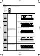
1. Input mode
For the input mode, you can choose one of the following five modes
• Addition
• Subtraction
• Directive
• Independent
• Phase
PHASE
IND
DIR
DOWN
UP
Input mode
Addition
UP
Subtraction
DOWN
Directive
DIR
Independent
IND
Phase
PHASE
Operation *Minimum input signal width 30 Hz: 16.7 ms; 5 kHz: 0.1 ms
IN1 or IN2 works as an input block
(gate) for the other input.
• Example where IN1 is the count input and IN2 is the input block (gate).
• Example where IN2 is the count input and IN1 is the input block (gate).
* “A” must be more than the minimum input signal width.
* “A” must be more than the minimum input signal width.
* “B” must be more than the minimum input signal width.
* IN1 and IN2 are completely independent, so there is no restriction on signal
timing.
IN1 is the count input and IN2 is the
addition or subtraction directive input.
IN2 adds at L level and subtracts at H
level.
IN1 is addition input and IN2 is subtrac-
tion input.
Addition when the IN1 phase advances
beyond IN2, and subtraction when the
IN2 phase advances beyond IN1.
0 1 2 3 n-3 n-2 n-1 n
n n-1 n-2 n-3 3 2 1 0
H
L
H
L
IN1
IN2
Counting (subtraction)
Counting (addition)
Blocked
AA AA
Reset
Count-up completed
AA AA
n n-1 n-2 n-4n-3 01
012 43nn-1
H
L
H
L
IN1
IN2
Counting (subtraction)
Counting (addition)
BlockedBlocked
Reset
Count-up completed
H
L
H
L
Counting
IN1
IN2
Addition Subtraction Addition
AA AA
012 34321012 34
Reset
Counting
IN1
IN2
H
L
H
L
01 2 343 2 11223
Reset
Counting
IN1
IN2
BB
001 2 123
Reset
H
L
H
L
Phase advance Phase retard
LC4H
02/2003