
Datasheet

SR-DSV10739− 25-11 −
MINAS-A5 Vol.1 Motor Business Unit, Appliances Company, Panasonic Corporation.
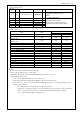
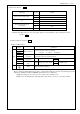
Function number
Setup value
Title symbol
a-contact
Invalid - 00h
Servo-Ready output ALM 01h
External brake release signal S-RDY 02h
Positioning complete output BRK-OFF 03h
At-speed output INP 04h
(Do not setup.) - 05h
Zero-speed detection output signal TLC 06h
Speed coincidence output ZSP 07h
(Do not setup.) - 08h
Alarm output 1 WARN1 09h
Alarm output 2 WARN2 0Ah
Positional command ON/OFF output P-CMD 0Bh
Positioning complete 2 INP2 0Ch
(Do not setup.) - 0Dh
Alarm attribute output ALM-ATB 0Eh
(Do not setup.) - 0Fh
Main power supply injection output P-ON 10h
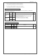
Attention :
・Same function can be assigned to 2 or more output signals.
・Control output pin set to invalid always has the output transistor turned OFF.
・Do not change the setup value shown in the table.
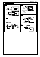
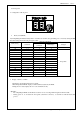
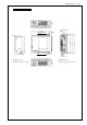
Others
Name Symbol
Connector
Pin No.
Description
Circuit
COM+
1
- Connect to the + terminal of an external DC power supply (12 to 24 V)
- Use a 12 V (±5%) to 24 V (±5%) power supply
――
Power
supply input
COM-
11
- Connect to the − terminal of an external DC power supply (12 to 24 V)
- The capacity of power supply varies depending on the input and output
circuit configuration. 0.5A or more is recommended.
――
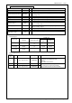
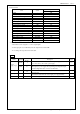
Frame ground
FG
Shell
26
- Internally connected to the earth terminal. ―
Signal ground
GND
12
- Signal ground
- Internally insulated from the control signal power supply (COM-).
―
Reserved -
24/25
- Don’t connect, please
―