
Datasheet


SR-DSV10739− 25-3 −
MINAS-A5 Vol.1 Motor Business Unit, Appliances Company, Panasonic Corporation.
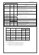
4. General Specifications
B Single-phase 220 – 240 V
+5%
-10%
50/60 Hz
Main circuit power
C Single-phase 220 – 240 V
+5%
-10%
50/60 Hz
B Single-phase 220 – 240 V
+5%
-10%
50/60 Hz
Input
power
supply
200V line
Control circuit
power
C Single-phase 220 – 240 V
+5%
-10%
50/60 Hz
Insular resistance
Endure the conditions of 1500V,1Minsensitive electric current20Ma between primary-earth
Temperature
Operation temperature: 0 – 50 degrees C Storage temperature: -20 – 65 degrees C
(Max .temperature guarantee: 80˚C for 72 hours)
Humidity
Operation and storage humidity 20~85%RH or less (no condensation)
Height above the sea Height above the sea level: 1,000 meters or less
Operation conditions
Vibration 5.88 m/s
2
or less, 10 – 60 Hz (Continuous operation at resonance point is not allowed)
Control method IGBT PWM method, sinusoidal drive
Encoder feedback
2500p/r (resolution:10000)5-serial incremental encoder
Input
Multi-function input 6,
Function of each multi-function input is assigned by the parameter.
Control signal
Output
Multi-function output 3
Function of each multi-function output is assigned by the parameter.
Input
Opt coupler input 1
Both open collector and line driver interface can be connected.
Line receiver input 1
High speed line driver interface can be connected. Pulse signal
Output
4 outputs
Line driver output for Encoder pulses (A/B/Z signal) or external feedback pulses (EXA/EXB/EXZ signal)
Open collector output also available for Z or EXZ signal
Communication USB USB interface to connect to computers for parameter setting or status monitoring.
Front Panel
2-digit 7-segment LED,2-digit RSW
Regeneration
External regen resistor only
Dynamic Brake Built-in
Basic Dimensions
Control Mode position control
Digital Input Deviation counter clear, Command pulse inhibition, Command scaling switch, Anti-vibration switch
Digital Output In-position
Max. Command Pulse
Frequency
500kpps (Optocoupler interface)
Command pulse input mode
Differential input. Selectable by parameter. ([1]Positive/Negative pulse [2]A/B quadrature [3]Pulse/Direction)
Command pulse scaling
(Electronic gear)
Applicable scaling ratio: 1/1000 – 1000
Any value of 1 – 20
20
can be set for both numerator (which corresponds to encoder resolution) and denominator
(which corresponds to command pulse resolution per motor revolution), but the combination has to be within the
range shown above.
Pulse Input
Smoothing Filter 1
st
order filter or FIR filter selectable for command input
Position Control
Anti-vibration Control Available
Auto-tuning
Operation command from the controller, with the inner workings command
of the amplifier, according to
identifying real-time load inertia, stiffness is setted automatically.
Scaling of feedback pulse Any number of pulses can be set up. (maximum setting number is encoder resolution)
Hardware error Overvoltage, undervoltage, over speed, overload, overheat, over current, encoder error, etc.
Protective Function
Software error Following error fault, command pulse scaling error, EEPROM error, etc.
Function
Common
Alarm data trace back Tracing back of alarm data is available