
User manual


№SR-ZSV00039 - 61 -
Motor Business Unit, Appliances Company, Panasonic Corporation
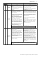
Protective
function
Main
Sub
Name Cause Action
0
Encoder
communication
disconnect error
protection
The communication between the encoder and the
servo drive was interrupted a certain number of times,
and the disconnection detection function started to
work.
Make the correct connection of the encoder wires.
Correct any wrong connections of the connector pin.
21
1
Encoder
communication
error protection
The data communication from the encoder is
erroneous. The data error is mainly due to noise.
The encode wires are connected but there is a
communication data error.
・ Make sure the encoder supply voltage is DC 5 V +/-
5% (4.75- 5.25 V). Bear this in mind especially
when the encoder wires are long.
・ Separate the encoder wires from the motor wires if
they are bundled together.
Connect the shield to FG.
23
0
Encoder commu
nication data err
or protection
The data communication from the encoder is not
erroneous, but the data itself is erroneous. The data
error is mainly due to noise. The encode wires are
connected but there is a communication data error.
・ Make sure the encoder supply voltage is DC 5 V +/-
5% (4.75- 5.25 V). Bear this in mind especially
when the encoder wires are long.
・ Separate the encoder wires from the motor wires if
they are bundled together.
Connect the shield to FG.
0
Position deviation
excess protection
Position deviation pulses have exceeded the setup of
Pr0.14 “Position deviation excess setup”
① The motor operation is not following the
command.
② The set value specified in Pr0.14 “Position
deviation excess setup” is too small.
1) Check if the motor rotates according to the position
command pulse input. Check the torque monitor to
see if the output torque has saturated. Perform a
gain tuning. Set the upper limit in Pr0.13 “1
st
torque limit” and Pr5.24 “Second torque limit
setting.” Make the encoder wiring connections to the
wiring diagram. Extend the acceleration time.
Reduce the load and lower the velocity.
2) Set a greater value in Pr0.14.
24
1
Velocity deviation
excess protection
The difference (speed deviation) between
in-position preset velocity and actual speed ex-
ceeded the Pr6.02 “Velocity deviation excess
setup”.
Note: When in-position preset velocity becomes zero
by force, such as the immediate stop because of the
command pulse inhibition (INH) and the positive/
negative overtravel limit, the speed deviation increases
in that moment. Also, the speed deviation increases
during startup of in-position preset velocity, so apply a
fully flexible setting.
・ Increase the Pr6.02 setting value.
・ Make longer the acceleration and deceleration dura-
tion of the in-position preset velocity, or improve the
following capability with the gain adjustment.
・ Disallow the velocity deviation excess detection.
(Pr6.02=0)
0
Over-speed
protection
The motor rotational speed has exceeded the set value
specified in Pr5.13 “Over-speed level setup”.
26
1
2
nd
over-speed
protection
The motor rotational speed has exceeded the set value
specified in Pr6.15 “2
nd
over-speed level setup”.
・ Stop giving excessive speed command.
・ Check the input frequency and scaling ratio for the
command pulse.
・ If there is an overshoot because the gain tuning is
poor, redo it.
・ Connect the encoder wires to the wiring diagram.
0
Command pulse
input frequency
error protection
The command pulse input frequency has exceeded 1.2
times the value specified in Pr5.32 “Command pulse
input maximum setup”.
・ Check the command pulse input.
27
2
Command pulse
multiplier error
protection
The scaling ratios used to set the Command pulse
counts per one motor revolution, the command
scaling numerators 1-4, and the denominator of
electronic gear are not appropriate.
・ Check the setting values for the command scaling.
28
0
Limit of pulse
replay error
protection
The output frequency for pulse regeneration has
exceeded the limit value.
・ Check the set value specified in Pr0.11
“Output pulse counts per one motor revolution” and
Pr5.03 “Denominator of pulse output division.”
・ To disable the detection, set Pr5.33 “Pulse
regenerative output limit setup” to 0.
(Continued)