No. SR-DSV10739 SPECIFICATIONS MODE L Product Name: AC Servo Drive Part Number: MINAS-LIQI series Issued on Oct. 26, 2011 (Revised on Jan.
SR-DSV10739 REVISIONS Date Page 2012/01/25 17-19 Rev. Description Itme 8 and 9 for EC/UL standards added.
SR-DSV10739- Contents 1. Scope··············································································································································1 2. Model Designation Code ···············································································································1 3. Product Line-up ·····························································································································2 4.
SR-DSV10739− 25-1 − 1. Scope These specifications relate to the servo driver for the AC servo system that is comprised of the AC servo motor manufactured and supplied by Motor Company, Panasonic Corporation, and the servo driver for driving this motor. This document of specifications defines products supplied on the basis of the OEM basic contract. 2.
SR-DSV10739− 25-2 − Rated Voltage Size Part Number MBDJT2207 Type B 1φ AC220-240V Rated Output 50W 100W 200W MBDJT2210 400W MCDJT3220 750W Type C MCDJT3230 1000W 1200W MINAS-A5 Vol.1 Motor MSMD5AZJ1* MSMD012J1* MSMD022J1* MHMD022J1* MSMD042J1* MHMJ042P1* MSMD082J1* MHMJ082P1* MHMD102J1* MHMJ102P1* MHMJ122P1* Motor Business Unit, Appliances Company, Panasonic Corporation.
SR-DSV10739− 25-3 − 4.
SR-DSV10739− 25-4 − 5.
SR-DSV10739− 25-5 − 220V Size C Name Plate Front Panel Rotary switch ERD716CMZ (ECE) X1:USB Connection UB-M5BR-DMP14-4S (JST) X2: Parallel I/O Connection 10226-52A2PE (3M) X3: Encoder Connection 3E106-2230 KV (3M) X4:Motor Connection Power Supply Connection 0138-76-S2060909 (DINKEL) Case U Motor Connection Terminal V W Regenerative Discharge Resistor Connection Terminal Control Power Supply Input Terminal e B1 B2 Screw L1C L2C L1 Main Power Supply Input Terminal L2 MINAS-A5 Vol.
SR-DSV10739− 25-6 − 6. Configuration of Connectors 6-1 USB Connector X1 By connecting to a computer or a controller via USB interface, the following operations are available parameter reference / change parameter save / load monitoring of status checking alarm status or alarm history Symbol Connector Pin No.
SR-DSV10739− 25-7 − Functions allocatable to Multi-function inputs Function Symbol Connector Pin No.
SR-DSV10739− 25-8 − -Change signal layout use Classificat ion No. Parameter Title Set range Unit Function 4 00 SI1 input selection 0∼00FFFFFFh - Assign function to SI1 input. this parameter is presented in hexadecimal. 000000**h 「**」with the function number. 4 4 4 4 4 01 02 03 04 05 SI2 input selection SI3 input selection SI4 input selection SI5 input selection SI6 input selection 0∼00FFFFFFh 0∼00FFFFFFh 0∼00FFFFFFh 0∼00FFFFFFh 0∼00FFFFFFh - Assign functions to SI2 to SI6 inputs.
SR-DSV10739− 25-9 − *3 Deviation counter clear input(CL)can be assigned only to SI7 input. Wrong assignment will cause Err33.6 Counter clear assignment error. *4 Command pulse inhibit input(INH)can be assigned only to SI10 input. Wrong assignment will cause Err33.7 Command pulse input inhibit input. Input signals (command pulse train) and their functions Suitable interface can be chosen from two kind of interface based on the specification of command pulses.
SR-DSV10739− 25-10 − Functions allocatable to Multi-function outputs Name Servo alarm Servo ready Symbol ALM S-RDY Motor holding break release Zero speed Torque limited InIn-position 2 BRK-OFF ZSP TLC INP INP2 Warning output1 WARN1 Warning output2 WARN2 P-CMD ALM-ATB position command output Alarm attribute output P-ON Main Power output Pin 8 10 9 - Description - Digital output to indicate alarm status.
SR-DSV10739− 25-11 − Function number Title symbol Invalid Servo-Ready output External brake release signal Positioning complete output At-speed output (Do not setup.) Zero-speed detection output signal Speed coincidence output (Do not setup.) Alarm output 1 Alarm output 2 Positional command ON/OFF output Positioning complete 2 (Do not setup.) Alarm attribute output (Do not setup.
SR-DSV10739− 25-12 − Input and output signal interface o−1 i−1 R 4.7K 7 VDC V DC + 50mA 以下 12 ∼24V − 12 ∼ 24V +:8,9,10 pin, −:11 pin Note) If you want to directly driver a relay,In parallel with or the relay. Please install the diode in the direction shown above. V DC VCE sat = 1.2V 12 ∼ 24V 7 4.7K D o−1 2,3,4,5,6,7 pin AM26C31( Equi val ent) Di−1 + − GND For open c ollector +:12,15,17 pin, −:14,16,18 pin 20.22 R Vp ON/OFF 21.
SR-DSV10739− 25-13 − 6-3 Encoder Connector X3 Description Encoder power supply output Connector Pin No. Symbol 1 E5V E0V (*Remark 1) 2 3 ―― 4 ―― Encoder Signal input/out put (Serial Signal) 5 PS 6 /PS Frame ground shell FG ―― * Remark 1) The E0V of the encoder power supply output is connected with the control circuit ground of the connector X3 .
SR-DSV10739− 25-14 − 6-5 Front panel ■ Configuration of Front panel ■ Rotary switch(RSW) By manipulating the RSW、Pr.0.03(selection of stiffness at real-time auto-gain tuning) was corrected by setting the RSW, and can be changed from the front panel gain control. Example)Pr0.03=8 The stiffness Parameter Pr0.
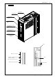
SR-DSV10739− 25-15 − 7. Dimensions External Dimension Size B Mounting Bracket (option) Name Plate Mounting Bracket (option) Base-Mounting TYPE (Standard: Mounted on the Back) MINAS-A5 Vol.1 Rack-Mounting TYPE (Option: Mounted on the Front) Motor Business Unit, Appliances Company, Panasonic Corporation.
SR-DSV10739− 25-16 − External Dimension Size C Mounting Bracket (option) Mounting Bracket (option) Base-Mounting TYPE (Standard: Mounted on the Back) MINAS-A5 Vol.1 Rack-Mounting TYPE (Option: Mounted on the Front) Motor Business Unit, Appliances Company, Panasonic Corporation.
SR-DSV10739− 25-17 − 8. Compliance with European EC Directive/ UL Standard 8-1 European EC directive European EC directive is applied to all electronic products that are exported to EU, have the inherent functions, and are directly sold to the consuming public. These products are obliged to be compliant with the unified EU safety standard and paste the CE marking indicating the compliance to the products.
SR-DSV10739− 25-18 − 8-2 Peripheral Device Configuration 8-2-1 Installation Environment Use the servo amplifier under the environment of pollution level 2 or 1 defined in IEC60664-1. (Example: Installed in the IP54 control panel.) 8-2-2 Power Supply 200V system : Single 220V - 240V 50/60Hz +10% - 15% (1) Use it under the environment of overvoltage category II defined in IEC60664-1.
SR-DSV10739− 25-19 − 8-2-6 Noise Filter for Signal Line and Reactor Install the noise filters for signal lines in all cables (power supply, motor, encoder, and interface cables), and the reactor in power supply cable. Recommended Surge absorber, Noise filter and Reactor Optional Part Number Part Number of Manufacturer Manufacturer Surge absorber DV0P4190 R A V-781BWZ-4 Okaya Electric Industries Noise filter for signal line DV0P1460 ZCAT3035-1330 TDK Reactor − RJ8035 KK-CORP.CO.
SR-DSV10739− 25-20 − 9. Compliance with SEMI F47 Instantaneous Stop Standard This function corresponds to the F47 power supply instantaneous stop standard in the SEMI standard during no/ light load condition. Useful when used in the semiconductor manufacturing equipment. Warning: [1] Not applicable to the amplifier which has a single phase 100V specification and a 24VDC specification for control power input.
SR-DSV10739− 25-21 − SAFETY PRECAUTIONS 10. Safety precautions ■ Danger and damage is expected to occur when the equipment is used ignoring safety precautions. The danger and damage is described in the following categories as indicated by the signs. DANGER Description of this sign indicates “urgent danger that may cause death or serious injury.” ATTENTION Description of this sign indicates “danger that may cause injury or property damage.
SR-DSV10739− 25-22 − SAFETY PRECAUTIONS (14)Wiring work is strictly allowed only for an engineer specializing electrical work. (15)A motor other than specified is not provided with a protection device. Protect a motor with an over current protection device, a ground-fault interrupter, overheating protection device, and emergency stop device, etc.
SR-DSV10739− 25-23 − SAFETY PRECAUTIONS (33)Do not fall or topple over the equipment when carrying or installing. (34)Do not climb the motor or do not place a heavy item on the motor. (35)Do not block radiation slits of the amplifier and do not put a foreign matter into the amplifier. (36)Do not use the equipment under direct sunlight. When storing the equipment, avoid direct sunlight and store under conditions of operating temperatures and humidity. (37)Be sure not to disassemble or modify the equipment.
SR-DSV10739− 25-24 − SAFETY PRECAUTIONS Servo driver's ambient temperature The driver's service life significantly depends on the ambient temperature. Make sure that the driver's ambient temperature (at 5cm distance from the driver) does not 5 cm exceed the specified operating temperature range. Servo driver 5 cm Operating temperature range: 0 to 50 C 5 cm Panasonic Corporation has made the best efforts to ensure quality of this product.
SR-DSV10739− 25-25 − 11. Life and Warranty 11-1 Life Expectancy of the Driver The Amplifier has 14,000 hours of life expectancy when used continuously under the following conditions. Definition of life: Life shall be defined as the time until capacity drop by 20% of electrolytic condenser from factory shipment status. Conditions Input power Working temperature.
SR-DSV10739− 25-26 − 12. Others - Precautions for export of this product and the equipment incorporating this product If the end user or end purpose of this product relates to military affairs, armament and so on, this product may be subject to the export regulations prescribed in "Foreign Exchange and Foreign Trade Control Law". To export this product, take thorough examination, and follow the required export procedure.
SR-DSV10739− 25-27 − Specifications by Model (Global Models) Model Power supply input Power device maximum current rating Current detector current rating Rotary encoder feedback signal Regenerative discharge resistor Mounting optional parts bracket MBDJT2207 Single-phase 220 V MBDJT2210 Single-phase 220 V MCDJT3220 Single-phase 220 V MCDJT3230 Single-phase 220 V 15A 15A 30A 30A 7A 10A 20A 30A Resolution: Resolution: Resolution: Resolution: 10000 P/r 10000 P/r 10000 P/r 10000 P/r Externally conn