ORDER NO. DSC1302004CE B26 Digital Camera Model No. DMC-XS1P DMC-XS1PC DMC-XS1PU DMC-XS1EB DMC-XS1EE DMC-XS1EF DMC-XS1EG DMC-XS1EP DMC-XS1GA DMC-XS1GC DMC-XS1GF DMC-XS1GK DMC-XS1GN DMC-XS1GT Colour (W)..........White Type (K)...........Black Type (R)...........Red Type (except PC) (WA)........White Type (only EB/EG/EP) (V)............Violet Type (only EB/EF/EG/EP/GC/GF/GN) © Panasonic Corporation 2013 Unauthorized copying and distribution is a violation of law.
TABLE OF CONTENTS PAGE 1 Safety Precautions -----------------------------------------------3 1.1. General Guidelines ----------------------------------------3 1.2. Leakage Current Cold Check ---------------------------3 1.3. Leakage Current Hot Check (See Figure. 1)--------3 1.4. How to Discharge the E.Capacitor on Flash Top P.C.B. ----------------------------------------------------4 2 Warning --------------------------------------------------------------5 2.1.
1 Safety Precautions 1.1. General Guidelines 1.3. 1. IMPORTANT SAFETY NOTICE There are special components used in this equipment which are important for safety. These parts are marked by 2. 3. 4. 5. 1. Plug the AC cord directly into the AC outlet. Do not use an isolation transformer for this check. 2. Connect a 1.5 kΩ, 10 W resistor, in parallel with a 0.15 μF capacitor, between each exposed metallic part on the set and a good earth ground, as shown in Figure. 1. 3.
1.4. How to Discharge the E.Capacitor on Flash Top P.C.B. CAUTION: • Be sure to discharge the E.Capacitor on Flash Top P.C.B. before disassembling. • Be careful of the high voltage circuit on Flash Top P.C.B. when servicing. [Discharging Procedure] 1. Put the insulation tube on the lead part of resistor (ERG5SJ102:1kΩ /5W). (An equivalent type of resistor may be used.) 2. Put the resistor between both terminals of E.Capacitor on the Flash Top P.C.B. for approx. 5 seconds. 3.
2 Warning 2.1. Prevention of Electrostatic Discharge (ESD) to Electrostatically Sensitive (ES) Devices Some semiconductor (solid state) devices can be damaged easily by static electricity. Such components commonly are called Electrostatically Sensitive (ES) Devices. The following techniques should be used to help reduce the incidence of component damage caused by electrostatic discharge (ESD). 1.
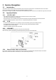
3 Service Navigation 3.1. Introduction This service manual contains technical information, which allow service personnel’s to understand and service this model. Please place orders using the parts list and not the drawing reference numbers. If the circuit is changed or modified, the information will be followed by service manual to be controlled with original service manual. 3.2. 3.2.1. Important Notice CCD FPC UNIT: • The image sensor (CCD FPC) unit which are connected to the lens unit with 3 screws.
3.3. General Description About Lead Free Solder (PbF) The lead free solder has been used in the mounting process of all electrical components on the printed circuit boards used for this equipment in considering the globally environmental conservation. The normal solder is the alloy of tin (Sn) and lead (Pb). On the other hand, the lead free solder is the alloy mainly consists of tin (Sn), silver (Ag) and Copper (Cu), and the melting point of the lead free solder is higher approx.
3.4. How to Define the Model Suffix (NTSC or PAL model) There are seven kinds of DMC-XS1, regardless of the colours. • a) DMC-XS1 (Japan domestic model) • b) DMC-XS1P/PC • c) DMC-XS1EB/EF/EG/EP • d) DMC-XS1EE • e) DMC-XS1GT • f) DMC-XS1GN • g) DMC-XS1PU/GA/GC/GF/GK What is the difference is that the “INITIAL SETTINGS” data which is stored in Flash-ROM mounted on Main P.C.B.. 3.4.1.
3.4.2. INITIAL SETTINGS: After replacing the Main P.C.B., make sure to perform the initial settings after achieving the adjustment by ordering the following procedure in accordance with model suffix of the unit. 1. IMPORTANT NOTICE: Before proceeding Initial settings, make sure to read the following CAUTIONS. 2. PROCEDURES: • Precautions: Read the above “CAUTION 1” and “CAUTION 2”, carefully. • Preparation: - Attach the Battery.
• Step 4. Display the INITIAL SETTING: While pressing [ MENU/SET ] button and “[ RIGHT ] of Cursor button” simultaneously, turn the Power off. The “INITIAL SETTINGS” menu is displayed. There are two kinds of “INITIAL SETTINGS” menu form as follows: [CASE 1. After replacing Main P.C.B.] When Main P.C.B. has just been replaced, all of the model suffix is displayed as follows. (Five pages in total) [CASE 2. Other than “After replacing Main P.C.B.”] • Step 5.
• Step 6. Set the model suffix in “INITIAL SETTINGS”: Press the “[ RIGHT ] of Cursor buttons”. The only set area is displayed, and then press the “[ RIGHT ] of Cursor buttons” after confirmation. (The unit is powered off automatically.) • Step 7. CONFIRMATION: Confirm the display of “PLEASE SET THE CLOCK” in concerned language when the unit is turned on again. When the unit is connected to PC with USB cable, it is detected as removable media.
4 Specifications The following specification is for DMC-XS1P/DMC-FH10P. Some specifications may differ depending on model suffix.
5 Location of Controls and Components The following description is for DMC-XS1P. Some descriptions may differ depending on model suffix.
6 Service Mode 6.1. Error Code Memory Function 1. General description This unit is equipped with history of error code memory function, and can be memorized 16 error codes in sequence from the latest. When the error is occurred more than 16, the oldest error is overwritten in sequence. The error code is not memorized when the power supply is shut down forcibly (i.e.
Error Code List The error code consists of 8 bits data and it shows the following information.
Important notice about “Error Code List” 1) About “*” indication: The third digit from the left is different as follows. - In case of 0 (example: 18001000) When the third digit from the left shows “0”, this error occurred under the condition of INITIAL SETTINGS has been completed. It means that this error is occurred basically at user side. - In case of 8 (example: 18801000) When the third digit from the left shows “8”, this error occurred under the condition of INITIAL SETTINGS has been released.
7 Service Fixture & Tools 7.1. Service Fixture and Tools The following Service Fixture and tools are used for checking and servicing this unit. 7.2. When Replacing the Main P.C.B. After replacing the Main P.C.B., be sure to achieve adjustment. The service software is available at “TSN Website”.
7.3. Service Position Check the Flash Top P.C.B., when servicing this DSC.(Refer to the following.) CAUTION. (When servicing Flash Top P.C.B.) 1. Be sure to discharge the E.Capacitor on Flash Top P.C.B.. Refer to “How to Discharge the E.Capacitor on Flash Top P.C.B.”. The E.Capacitor voltage is not lowered soon even if the AC Cord is unplugged or the battery is removed. 2. Be careful of the high voltage circuit on Flash Top P.C.B.. 3.
8 Disassembly and Assembly Instructions 8.1. Disassembly Flow Chart This is a disassembling chart. When assembling, perform this chart conversely. 8.2. P.C.B.
8.3. Disassembly Procedure No. Item 1 Rear Case Unit Fig (Fig. D1) 2 (Fig. D2) Rear Op Plate Unit (Fig. D3) 3 Front Case Unit (Fig. D4) 4 LCD Unit (Fig. D5) 5 Frame Plate (Fig. D6) 6 Top Case Unit (Fig. D7) 7 Flash Top P.C.B. (Fig. D8) (Fig. D9) 8 Lens Unit (W/CCD) (Fig. D10) 9 Main P.C.B. Speaker (Fig. D11) (Fig. D12) 10 Battery Door Unit (Fig. D13) 8.3.1.
8.3.2. Removal of the Rear Op Plate Unit (Fig. D2) (Fig.
8.3.3. Removal of the Front Case Unit 8.3.4. Removal of the LCD Unit (Fig. D4) (Fig.
8.3.5. Removal of the Frame Plate (Fig. D6) 8.3.6. Removal of the Top Case Unit (Fig. D8) (Fig.
8.3.7. Removal of the Flash Top P.C.B. 8.3.8. Removal of the Lens Unit (W/CCD) (Fig. D10) 8.3.9. (Fig. D9) Removal of the Main P.C.B. and Speaker (Fig.
[ When Installing ] CATION: Before soldering the Terminal A (Connecting part of Main P.C.B. and Frame Unit). Before soldering the Terminal A, make sure to tighten the “Screw (F)” first in order to eliminate the gap between Main P.C.B. and Frame Unit. Otherwise, soldered terminal A part may be damaged after assembling. (Fig.
8.3.10. Removal of the Battery Door Unit (Fig. D13) NOTE: (When Installing) Make sure to confirm the following points when installing: • The Screw is tightened enough. • Installing conditions are fine. (No distortion, no abnormalspace.) • No dust and/or dirt on Lens surfaces. • LCD image is fine. (No dust and dirt on it, and no gradient images.
8.4. Removal of the CCD FPC Unit When remove the CCD FPC Unit once (the screw (G) is loosened even a little), the optical tilt adjustment is required. When loosen the screw (G), necessary the optical tilt adjustment at the end of assembling. (Refer to item “9.3.2.”) To prevent the CCD FPC Unit from catching the dust and dirt, do not remove the CCD FPC Unit except for replacing. (Fig.
9 Measurements and Adjustments 9.1. Introduction When servicing this unit, make sure to perform the adjustments necessary based on the part(s) replaced. Before disassembling the unit, it is recommended to back up the camera data stored in Flash-ROM as a data file. IMPORTANT NOTICE (After replacing the Main P.C.B.) After replacing the Main P.C.B., it is necessary to use the “DIAS” software to allow the release of adjustment flag(s). The Adjustment software “DIAS” is available at “TSN Website”.
9.2.2. Flash-ROM Data Backup Number of necessary adjustment items decreases by copying the backup data to new Main P.C.B. when adjustment data in old Main P.C.B. is usually read by ROM_BACKUP “DSC→SD”. It is recommended to backup the Flash-ROM data as the way of return when trouble occurs before disassembling the unit depending on each case. [ ROM_BACKUP (Method of Non-PC backup) ] 1. Insert the memory card into the camera. 2. Set the camera to “Temporary cancellation of the initial settings”. 3.
9.3. 9.3.1. Details of Electrical Adjustment How to execute the Electrical Adjustment It is not necessary to connect the camera to a PC to perform adjustments. “Flag reset operation” and “Initial setting operation” are required when carrying out the alignment, follow the procedure below. 9.3.1.1. Startup Electrical Adjustment mode 1. Release the initial settings. 2. Insert a recordable memory card (32MB or more). (Without a momery card, the automatic adjustment can not executed.) 3.
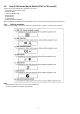
9.3.1.3. Execute Adjustment (In case of “OIS Adjustment”) 1. Perform step “9.3.1.1.” to “9.3.1.2.”, to reset the OIS flag status “F” (Set) to “0” (Reset) 2. Press “[ W ] side of the Zoom button” after Flag reset. OIS Adjustment screen is displayed on the LCD panel. (Refer to Fig.3-3) 3. Press the [ Shutter ] button. The adjustment will start automatically. Fig.3-3 4. When the adjustment is completed successfully, adjustment report menu appears with Green OK on the LCD monitor. (Refer to Fig.3-4) Fig.
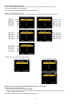
9.3.2. Adjustment Specifications The following matrix table shows the relation between the replaced part and the Necessary Adjustment. When a part is replaced, make sure to perform the necessary adjustment(s) in the order indicated. The table below shows all the information necessary to perform each adjustment.
9.4. 9.4.1. After Adjustment Initial Setting Since the initial setting has been released to execute the built-in adjustment software, it should be set up again before shipping the camera to the customer. Refer to the procedure described in “3.4.2. INITIAL SETTINGS” for details. [ IMPORTANT ] 1. The initial setting should be done again after completing the alignment. Otherwise, the camera will not work properly.
10 Maintenance 10.1. Cleaning Lens and LCD Panel Do not touch the surface of lens and LCD Panel with your hand. When cleaning the lens, use air-Blower to blow off the dust. When cleaning the LCD Panel, dampen the lens cleaning paper with lens cleaner, and the gently wipe the its surface. Note: The Lens Cleaning KIT ; VFK1900BK (Only supplied as 10 set/Box) is available as Service Aid.
11 Block Diagram 11.1. Overall Block Diagram OVERALL BLOCK DIAGRAM (25mm ~ 125mm) CCD 1/2.33" 16.1 MEGA PIX ZOOM OIS UNIT IRIS SHUTTER MAIN P.C.B. CCD SIGNAL PROCESSOR (12MHz) CDS, AGC, A/D, TG, CCD DRIVER MEMORY CARD FOCUS COLOR LCD PANEL 2.
11.2. Flash / Top Block Diagram 11.3. Sub Operation Block Diagram FLASH TOP BLOCK DIAGRAM SUB OPERATION BLOCK DIAGRAM FLASH TOP P.C.B. CL8001 (UNREG+) FP8001 18-21 TL8003 T8001 LAMP(+) F8001 CL8002 3 2 5 1 SUB OPERATION P.C.B.
12 Wiring Connection Diagram 12.1. Interconnection Diagram FLASH TOP P.C.B.