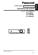
LCD Projector Commercial Use Operating Instructions Model No. PT-LB20NTE PT-LB20E PT-LB20SE PT-LB20VE POWER INPUT VIDEO AUTO SETUP RGB MENU ENTER SHUTTER FREEZE STD VOLUME D.ZOOM INDEX WINDOW PROJECTOR Before operating this product, please read the instructions carefully and save this manual for future use.
Dear Panasonic Customer: This instruction booklet provides all the necessary operating information that you might require. We hope it will help you to get the most out of your new product, and that you will be pleased with your Panasonic LCD projector. The serial number of your product may be found on its bottom. You should note it in the space provided below and retain this booklet in case service is required.
CAUTION: To assure continued compliance, follow the attached installation instructions, which includes using the provided power cord and shielded interface cables when connecting to computer or peripheral device. If you use serial port to connect PC for external control of projector, you must use optional RS-232C serial interface cable with ferrite core. Any unauthorized changes or modifications to this equipment will void the user’s authority to operate.
-ENGLISH
Preparation IMPORTANT SAFETY NOTICE ...2 Precautions with regard to safety .........................................6 Accessories ...............................10 Before use ..................................11 Location and function of each part...........................................13 Getting started Setting-up...................................18 Projection methods, Projector position, Projection distances Connections...............................
Precautions with regard to safety WARNING If you notice smoke, strange smells or noise coming from the projector, disconnect the mains plug from the mains socket. B Do not continue to use the projector in such cases, otherwise fire or electric shocks could result. B Check that no more smoke is coming out, and then contact an Authorised Service Centre for repairs. B Do not attempt to repair the projector yourself, as this can be dangerous.
ENGLISH-7 Preparation Do not do anything that might damage the mains lead or the mains plug. B Do not damage the mains lead, make any modifications to it, place it near any hot objects, bend it excessively, twist it, pull it, place heavy objects on top of it or wrap it into a bundle. B If the mains lead is used while damaged, electric shocks, short-circuits or fire may result. B Ask an Authorised Service Centre to carry out any repairs to the mains lead that might be necessary.
During a thunderstorm, do not touch the projector or the cable. B Electric shocks can result. Do not use the projector in a bath or shower. B Fire or electric shocks can result. Do not look into the lens while the projector is being used. B Strong light is emitted from the projector’s lens. If you look directly into this light, it can hurt and damage your eyes. B Be especially careful not to let young children look into the lens. In addition, disconnect the mains plug when you are away from the projector.
ENGLISH-9 Preparation Always disconnect all cables before moving the projector. B Moving the projector with cables still attached can damage the cables, which could cause fire or electric shocks to occur. Do not place any heavy objects on top of the projector. B Failure to observe this may cause the projector to become unbalanced and fall, which could result in damage or injury. Do not short-circuit, heat or disassemble the batteries or place them into water or fire.
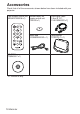
Accessories Check that all of the accessories shown below have been included with your projector. Card remote control unit Lithium battery for (N2QADC000008 x1) remote control unit (CR2025 x1) POWER RGB signal cable [1.8 m (5´10˝), K1HA15DA0002 x1] INPUT VIDEO AUTO SETUP RGB MENU ENTER FREEZE SHUTTER STD VOLUME D.
Caution when moving the projector Be sure to attach the lens cover before moving the projector. The projection lens is extremely susceptible to vibration and shocks. When moving the projector, use the accessory carrying bag. When placing the projector inside the carrying bag, position it so that the lens is facing upward. Do not put anything else in the bag other than the projector and the cables. Cautions regarding setting-up Avoid setting up in places which are subject to vibration or shocks.
Notes on use In order to get the best picture quality Draw curtains or blinds over any windows and turn off any lights near the screen to prevent outside light or light from indoor lamps from shining onto the screen. Do not touch the surfaces of the lens with your bare hands. If the surface of the lens becomes dirty from fingerprints or anything else, this will be magnified and projected onto the screen. Moreover, when not using the projector, retract the lens and then cover it with the lens cover.
Preparation Location and function of each part Projector # $ % ' & * ) ' ( # Projector control panel (page 16) $ Zoom ring (page 25) % Focus ring (page 25) & Security lock This can be used to connect a commercially-available theft-prevention cable (manufactured by Kensington). This security lock is compatible with the Microsaver Security System from Kensington. ' Leg adjuster buttons (L/R) (page 25) These buttons are used to unlock the front adjustable legs.
Projector $ %$ # ( ' & # Connector panel (page 15) $ Air outlet port Do not cover this port. % Speaker & Front adjustable legs (L/R) (page 25) ' Air inlet port, Air filter (page 54) Do not cover this port. ( Lamp unit cover (page 55) NOTE: B During projection of an image, the cooling fan will operate, emitting a small noise as it operates. This noise may change depending on the ambient temperature. Turning the lamp on or off will cause this noise to increase a little.
Preparation Connector panel $ % # & ' ) * ( # Power input socket (AC IN) (page 24) The accessory mains lead is connected here. Do not use any mains lead other than the accessory mains lead. $ SERIAL connector (pages 21, 22 and 64) This connector is used to connect a personal computer to the projector in order to control the projector externally. (RS-232C compatible) % RGB1 IN connector (pages 21 and 22) This connector is used to input RGB signals and YPBPR signals.
Projector control panel Menu operation # $ % & ' ( * ) +, Remote control unit ' ) POWER ( INPUT VIDEO RGB * + AUTO SETUP MENU , ENTER . / FREEZE SHUTTER 0 STD VOLUME D.ZOOM INDEX WINDOW 1 PROJECTOR 2 # RGB INPUT indicator This indicator illuminates when a signal is being input to the connector (RGB1 IN or RGB2 IN) selected using the input select buttons. It also illuminates while the direct power off function is operating.
ENGLISH-17 Preparation % TEMP indicator (page 52) This indicator illuminates if an abnormally high temperature is detected inside the projector or around it. If the temperature rises above a certain level, the power supply will be turned off automatically and the indicator will flash. & Illumination sensor (page 39) This sensor detects the luminance when the “DAYLIGHTVIEW” function is operating. Do not cover the projector and do not place any object on the projector when using it.
Setting-up Projection methods In way of installing projector, any one of the following four projection methods are used. Select whichever projection method matches the setting-up method. (The projection method can be set from the “OPTION” menu. Refer to pages 46 and 47 for details.
Projector position Screen H1 L 81.2 mm (3-3/16˝ ) Bottom edge of screen L: Projection distance SH: Image height SW:Image width H1: Distance from centre of lens to bottom edge of projected image SW L Screen Projection distances PT-LB20NTE/PT-LB20E 4:3 Screen size (diagonal) 0.84 m(33˝) 1.02 m(40˝) 1.27 m(50˝) 1.52 m(60˝) 1.78 m(70˝) 2.03 m(80˝) 2.29 m(90˝) 2.54 m(100˝) 3.05 m(120˝) 3.81 m(150˝) 5.08 m(200˝) 6.35 m(250˝) 7.62 m(300˝) Projection distance (L) Wide (LW) Telephoto (LT) — 1.2 m(3´11˝) 1.
PT-LB20SE 4:3 Screen size (diagonal) 0.84 m(33˝) 1.02 m(40˝) 1.27 m(50˝) 1.52 m(60˝) 1.78 m(70˝) 2.03 m(80˝) 2.29 m(90˝) 2.54 m(100˝) 3.05 m(120˝) 3.81 m(150˝) 5.08 m(200˝) 6.35 m(250˝) 7.62 m(300˝) Projection distance (L) Wide (LW) Telephoto (LT) — 1.2 m(3´11˝) 1.5 m(4´11˝) 1.8 m(5´10˝) 2.1 m(6´10˝) 2.4 m(7´10˝) 2.8 m(9´2˝) 3.0 m(9´10˝) 3.7 m(12´1˝) 4.6 m(15´1˝) 6.1 m(20´) 7.6 m(24´11˝) 9.2 m(30´2˝) Height position (H1) 0.08 m(3-1/8˝) 0.09 m(3-17/32˝) 0.11 m(4-5/16˝) 0.14 m(5-1/2˝) 0.16 m(6-9/32˝) 0.
Connections B Read the instruction manual for each peripheral device carefully before connecting it. B Turn off the power supply for all peripheral devices before making any connections. B If the cables necessary for connection are not included with the peripheral device or available as an option, you may need to prepare a proper cable for the device concerned. B If there is a lot of jitter in the video signal, the projected image may flicker.
Connecting to video equipment Computer for control use DIN 8-pin (male) D-sub15-pin (male) - BNCx5 (male) adapter cable Red (connect to PR signal connector) Blue (connect to PB signal connector) Green (connect to Y signal connector) DVD player (with component video connectors) Serial adapter (ET-ADSER : sold separately) BNC/RCA adapter DVD player Video deck NOTE: B If the signal cables are disconnected or if the power supply for the computer or video deck is turned off while “D.
Preparation for the remote control unit Insert the accessory lithium battery while making sure that the polarities are correct. # While pushing the battery holder tab to the right, pull out the battery holder. Back side Pull out $ Insert the battery into the battery holder so that the + side is facing upward. Match the “+” surface of the battery with the “+” marked side of the battery holder. % Insert the battery holder. NOTE: B Do not drop the remote control unit.
Turning on the power Before turning on the power 1. Ensure that all peripheral devices are connected properly. 2. Remove the lens cover. POWER $ INPUT VIDEO # Mains lead RGB & AUTO SETUP MENU ENTER ) SHUTTER FREEZE STD VOLUME D.ZOOM INDEX WINDOW * ( POWER button PROJECTOR Lens cover ' the accessory mains lead to the AC IN # Connect socket. BThe POWER button on the projector will illuminate red. the POWER button. $ Press BThe POWER button on the projector will flash green.
the input select button to select the & Press input signal. Input select button Remote control unit Changing signals Input select buttons Changing signals RGB1 RGB2 S-VIDEO VIDEO VIDEO VIDEO S-VIDEO NETWORK RGB RGB1 RGB2 NETWORK BA picture will be projected in accordance with the selected input signal. BWhen a YPBPR signal is being input, “YPBPR” will be displayed instead of “RGB”. B“NETWORK” is for PT-LB20NTE only.
Turning off the power POWER button # POWER INPUT VIDEO RGB AUTO SETUP MENU ENTER FREEZE $ SHUTTER STD VOLUME D.ZOOM INDEX WINDOW PROJECTOR % Mains lead the POWER button. # Press B“POWER OFF” is displayed on the screen. POWER OFF OK CANCEL the I or H button to select “OK”, and $ Press then press the ENTER button. BThe lamp unit will switch off and the picture will stop being projected. (The POWER button on the projector will illuminate orange while the cooling fan is still operating.
You can disconnect the mains lead during projection or immediately after use and move the projector. The cooling fan will operate by the internal power supply to cool down the lamp. B When this function is used, it may take more time for the lamp to turn back on again compared to when the lamp cools down with the mains lead connected. B Do not put the projector in a bag while the POWER button on the projector is illuminated.
Correcting keystone distortion and automatic positioning (AUTO SETUP) This projector detects its degree of tilt and the input signal. Keystone distortion and the position of the image can then be corrected automatically in accordance with the input signal. POWER Press the AUTO SETUP button. (When the projected image has caused keystone distortion) INPUT VIDEO AUTO SETUP RGB MENU Screen ENTER SHUTTER FREEZE Projected image STD VOLUME D.
Turning off the picture and sound momentarily (SHUTTER) The “SHUTTER” function can be used to momentarily turn off the picture and sound from the projector when the projector is not being used for short periods of time, such as during breaks in meetings or when carrying out preparation. The projector uses less power in “SHUTTER” mode than it does in normal projection mode. POWER INPUT VIDEO RGB AUTO SETUP MENU Press the SHUTTER button. B The picture and sound will be turned off.
Enlarging the picture (D.ZOOM) POWER Press the D.ZOOM +/- button. INPUT VIDEO AUTO SETUP RGB MENU ENTER FREEZE SHUTTER STD D.ZOOM VOLUME INDEX WINDOW B The picture will then be enlarged to 1.5 times the normal size. [ PROJECTOR The remote control unit functions during D.ZOOM (digital zoom) Press the D.ZOOM +/- buttons to change the enlargement ratio. Press the F,G,IandHbuttons to move the enlarged area which you want to project. Press the MENU button to return to the normal screen.
Displaying two screens (INDEX WINDOW) This function lets you store a picture which is being projected into memory, so that you can display a still picture and a moving picture on the screen. AUTO SETUP Press the INDEX WINDOW button. B The aspect ratio of the screen changes and the image is vertically elongated in comparison to a normal image. B When NETWORK is selected, the screen display will be switched between four window style, index style, and 16 Index style. (PT-LB20NTE only.
On-screen menus Menu screens The various settings and adjustments for this projector can be carried out by selecting the operations from on-screen menus. The general arrangement of these menus is shown below. MAIN MENU MENU KEYSTONE PICTURE POSITION INDEX WINDOW SHUTTER VOLUME LANGUAGE OPTION SECURITY NETWORK SELECT ENTER PICTURE menu (page 37) When an RGB signal is being input or NETWORK is selected PICTURE PICTURE MODE DYNAMIC CONTRAST 32 BRIGHT 32 SHARPNESS 0 COLOR TEMP.
POSITION POSITION DOT CLOCK 32 CLOCK PHASE 16 ASPECT 4:3 RESIZING ON FRAME LOCK OFF STANDARD SELECT ENTER RETRN B When an S-VIDEO/VIDEO signal is being input, “DOT CLOCK”, “CLOCK PHASE” and “FRAME LOCK” settings will not be displayed. INDEX WINDOW function (page 31) SHUTTER function (page 29) VOLUME adjustment Press the ENTER button, and then press the I or H button to adjust the volume.
Menu operation guide POWER # Press the MENU button. The “MAIN MENU” will be displayed. INPUT VIDEO AUTO SETUP RGB MENU ENTER SHUTTER FREEZE STD VOLUME D.ZOOM MENU KEYSTONE PICTURE POSITION INDEX WINDOW SHUTTER VOLUME LANGUAGE OPTION SECURITY NETWORK SELECT ENTER EXIT INDEX WINDOW PROJECTOR Menu operation (on connector panel) NOTE: B Press the MENU button to return to the previous screen. 34-ENGLISH $ Press the F or G button to select an item.
& Press the F or G button to select an item, and then press the I or H button to change or adjust the setting. An individual adjustment screen such as the one shown below will be displayed for bar scale items. BRIGHT 32 The bar scale will turn green when any adjustment changes the setting from the factory set value. Unavailable on-screen menu items This projector has unadjustable items and unusable functions depending on the signal being input.
Correcting keystone distortion Keystone distortion is corrected automatically when the projector’s automatic setup function is used, but this correction will not apply if the screen itself is tilted. In such cases, you can correct the keystone distortion manually with the following procedure. Vertical keystone distortion correction only. KEYSTONE 0 Vertical keystone distortion correction Operation Press the H button. Press the I button.
Adjusting the picture When an RGB signal is being input or NETWORK is selected PICTURE PICTURE MODE DYNAMIC CONTRAST 32 BRIGHT 32 SHARPNESS 0 COLOR TEMP. STANDARD W-BAL R 32 W-BAL G 32 W-BAL B 32 DAYLIGHTVIEW AI ON SIGNAL MODE XGA STANDARD SELECT ADJ RETRN When NETWORK is selected, “W-BAL R/G/B” settings will not be displayed. (PT-LB20NTE only) When an YPBPR signal is being input PICTURE PICTURE MODE STANDARD CONTRAST 32 BRIGHT 32 COLOR 32 TINT 32 SHARPNESS 6 COLOR TEMP.
CONTRAST COLOR TEMP. This adjusts the contrast of the picture. (Adjust the “BRIGHT” setting first if required before adjusting the “CONTRAST” setting.) The picture is bright: I button The picture is dark: H button COLOR TEMP. BRIGHT This adjusts the darker areas (black areas) in the picture. Black areas are too light: I button Dark areas are too solid: H button COLOR (S-VIDEO/VIDEO/YPBPR only) The colour is too deep: I button The colour is too pale: H button TINT (NTSC/NTSC 4.
DAYLIGHTVIEW W-BAL This adjusts the vividness of the projected images when the projector is used under bright lighting. Press the ENTER button to display the “DAYLIGHTVIEW” screen. W-BAL DAYLIGHTVIEW MODE AUTO W-BAL RETRN SELECT ADJ MODE MODE AUTO [ ON [ When fluorescent lamps are used for room lighting. When incandescent lamps are used for room lighting. NOTE: B “W-BAL” is disabled when “MODE” in “DAYLIGHTVIEW” is set to “OFF”.
TV-SYSTEM SIGNAL MODE (S-VIDEO/VIDEO only) TV-SYSTEM AUTO (RGB/YPBPR/NETWORK only) This displays the type of signal which is currently being projected. Refer to the list on page 62 for details on each type of signal. [ NTSC [ NTSC4.43 [ PAL [ PAL-M [ PAL-N [ SECAM This should normally be set to “AUTO”. If the signal is of such poor quality that the correct format cannot be automatically distinguished, change the setting manually to the required TV system.
Adjusting the position Press the F or G button on the projector or remote control unit to select an item, and then press the I or H button to change the setting. For items with bar scales, press the ENTER button or the I or H button to display the adjustment screen, and then press the I or H button to make the adjustment.
ASPECT (S-VIDEO/VIDEO/480i, 576i, 480p and 576p YPBPR only) ASPECT AUTO [ 4:3 S4:3 The size of the input signal is compressed to 75% and projected. (This is useful for projecting a picture with a 4:3 aspect ratio onto a 16:9 screen.) [ 16:9 [ S4:3 AUTO (S-VIDEO only) When an S1 video signal is being input, the aspect ratio is changed automatically to project a 16:9 picture. 4:3 The input signal is projected without change. 16:9 The picture is compressed to a ratio of 16:9 and projected.
RESIZING This should normally be set to “ON”. (This setting is only for signals which have lower resolutions than the LCD panels. Refer to page 62 for details.) ON The pixel resolution of the input signal is converted to the same resolution as the LCD panels before being projected. This may sometimes cause problems with the quality of the picture. OFF The input signal is projected at its original resolution, with no pixel conversion.
Changing the display language Press the F or G button on the projector or remote control unit to select a language, then press the ENTER button to accept the setting. LANGUAGE DEUTSCH FRANÇAIS ESPAÑOL ITALIANO PORTUGUÊS SVENSKA NORSK DANSK POLSKI CESTINA MAGYAR ENGLISH ▼ SELECT ENTER LANGUAGE RETRN ENGLISH ▲ ENGLISH 中文 日本語 SELECT 44-ENGLISH ENTER RETRN Indicates the language which is currently set.
Option settings OPTION OSD ON AUTO SEARCH ON AUTO SIGNAL ON AUTO KEYSTN ON RGB2 SELECT INPUT AUTO RGB/YPB PR VGA60/480p 480p SXGA MODE SXGA NR OFF BLACKBOARD OFF ▼ SELECT ADJ RETRN OPTION ▲ AUTO SEARCH This should normally be set to “ON” ON When the power is turned on and “AUTO SETUP” is running, the projector detects which signals are being input, and uses these signals for projection. (If a picture is being projected, the signal source is not automatically changed.
RGB2 SELECT Noise Reduction (NR) This setting is used to select the function of the RGB2 IN/1 OUT connector. (S-VIDEO/VIDEO only) If the signal is of such poor quality that picture interference appears, set “NR” to “ON”. To turn off the “NR” feature, set to “OFF”. RGB/YPBPR RGB/YPB PR AUTO [ RGB [ YPB PR This should normally be set to “AUTO”. RGB or YPBPR is selected automatically depending on the synchronising signal status.
DESK/CEILING DESK [ CEILING This setting should be changed in accordance with the projector setting-up method. (Refer to page 18.) DESK When the projector is placed on a desk or similar. CEILING When the projector is suspended from a ceiling using the ceiling bracket (sold separately). FAN CONTROL FAN CONTROL STANDARD [ HIGH Set “FAN CONTROL” to “HIGH”, when using this projector at high elevations (above 1 400 m) only. LAMP POWER LAMP POWER HIGH [ LOW This setting changes the lamp brightness.
CONTROL KEY To disable the buttons on the projector, set “CONTROL KEY” to “OFF”. A confirmation screen will then be displayed. Select “OK” by using I or H button. To use the buttons on the projector, set to “ON” by using the remote control unit. AUTO POW.OFF If no signal is input to the projector for the duration of the period you set, the projector will return to standby mode. The period can be set from 15 minutes to 60 minutes in 5 minute intervals. If you don’t use this feature, set it to “DISABLE”.
Setting up the security function This projector is equipped with a security function. A password input screen can be displayed, or a company URL can be set up and displayed at the bottom of the projected image. MENU KEYSTONE PICTURE POSITION INDEX WINDOW SHUTTER VOLUME LANGUAGE OPTION SECURITY NETWORK SELECT ENTER EXIT INPUT PASSWD The password input screen can be displayed when the power is turned on. All of the controls other than the POWER button are disabled unless the password is entered correctly.
NOTE: B The entered password will appear as . It will not be displayed on the screen. B If you enter the wrong password, the letters “PASSWORD” and “NEW” will become red. Enter the correct password again. TEXT DISPLAY You can set text to be displayed at the bottom of the projected image at all times. ON “TEXT DISPLAY” is enabled. OFF “TEXT DISPLAY” is disabled. TEXT CHANGE The text which is displayed when “TEXT DISPLAY” is set to “ON” can be changed.
Network setup (PT-LB20NTE only) You need to make adjustments on some items when controlling the projector with a personal computer by means of the wireless network. Refer to the accessory CD-ROM for details. NETWORK NETWORK 1 NAME CHANGE LB20NT INPUT PASSWD OFF AMEND PASSWD WEB CONTROL ON STATUS DEFAULT SELECT ENTER RETRN INPUT PASSWD Set to “ON” if you want password confirmation to be used when controlling the projector with a personal computer by means of the wireless network.
When the TEMP indicator and the LAMP indicator are illuminated There are two indicators on the control panel of the projector which give information about the operating condition of the projector. These indicators illuminate or flash to warn you about problems that have occurred inside the projector, so if you notice that one of the indicators is on, turn off the power and check the table below for the cause of the problem.
LAMP indicator Indicator display Illuminated (red) It is nearly time to Problem replace the lamp unit. Flashing (red) An abnormality has been detected in the lamp circuit. B This occurs when B Wait for a while B Disconnect the the operation time until the lamp unit mains lead by for the lamp unit is cools down before following the nearing 1 800 turning the power procedure on hours (when back on again.
Cleaning and replacing the air filter If the air filter becomes clogged with dust, the internal temperature of the projector will rise, the TEMP indicator will illuminate and the projector’s power will turn off (the TEMP indicator will flash after the power is turned off). The air filter should be cleaned every 100 hours of use. Cleaning Replacement procedure Use a vacuum cleaner to clean off any accumulated dust. # Turn off the power and disconnect the mains lead.
Replacing the lamp unit When replacing the lamp, allow it to cool for at least one hour before handling it. B The lamp cover gets very hot, and touching it can cause burns. Notes on replacing the lamp unit B The light generating lamp is made of glass, so dropping it or allowing it to hit hard objects may cause it to burst. Be careful when handling the lamp. B Dispose of the removed old lamp with the same care that would be taken with a fluorescent light.
On-screen display LAMP indicator Displayed for 30 seconds. Pressing any More than 1 800 hours button will clear the display. More than 2 000 hours Illuminates red during image projection and standby mode. Remains displayed until any button is pressed. Lamp unit replacement procedure NOTE: B If the lamp usage time has passed 2 000 hours (when “LAMP POWER” has been set to “HIGH” and when “AI” has been set to “OFF”), the projector will switch to standby mode after approximately 10 minutes of operation.
NOTE: B Be sure to install the lamp unit and the lamp unit cover securely. If they are not securely installed, it may cause the protection circuit to operate so that the power cannot be turned on. ( Connect the mains lead. ) Press the POWER button so that a picture is projected onto the screen.
Before calling for service Before calling for service, check the following points. Problem Possible cause Power does not B The mains lead may not be connected. turn on. B The main power supply is not being supplied to the mains socket. B TEMP indicator is illuminated or flashing. B LAMP indicator is illuminated or flashing. B The lamp unit cover has not been securely installed. No picture B The video signal input source may not be appears. connected properly.
Problem Possible cause Page The picture does B The signal format (“TV-SYSTEM”) may not be set 40 not display correctly. correctly. – B There may be a problem with the video tape or other signal source. B A signal which is not compatible with the projector 62 may be being input. Picture from B The cable may be too long. – computer does B The external video output for the laptop computer – not appear. may not be set correctly.
Specifications Power supply: Power consumption: 100 V - 240 V ~, 50 Hz/60 Hz 220 W [During standby (when fan is stopped): Approx. 4 W] 2.5 A - 1.3 A Amps: LCD panel: Panel size (diagonal): PT-LB20NTE/PT-LB20E/PT-LB20SE: 0.7 type (17.78 mm) PT-LB20VE: 0.6 type (15.
During YPBPR input/output: Y: PB, PR : During RGB input/output: R.G.B.: G.
Appendix List of compatible signals Mode Scanning Picture Resizing*3 Display Dot clock frequency quality*2 resolution frequency LB20NTE Format LB20NTE H V (dots)*1 (MHz) LB20E LB20SE LB20E LB20SE (kHz) (Hz) LB20VE LB20VE NTSC/NTSC4.
Projection dimensions calculation methods If the screen size (diagonal) is SD (m), then the following formula is used to calculate the projection distance for the wide lens position (LW) and the projection distance for the telephoto lens position (LT). SD H1 SH 4:3 LW/LT PT-LB20NTE/PT-LB20E PT-LB20SE PT-LB20VE SW LW=0.030xSD/0.0254-0.037 LT=0.036xSD/0.0254-0.037 LW=0.031xSD/0.0254-0.038 LT=0.037xSD/0.0254-0.038 LW=0.035xSD/0.0254-0.037 LT=0.042xSD/0.0254-0.
Using the SERIAL connector The serial connector which is on the connector panel of the projector conforms to the RS-232C interface specification, so that the projector can be controlled by a personal computer which is connected to this connector. Connection Communications settings Computer SERIAL(female) DIN 8-pin (male) Serial adapter (ET-ADSER : sold separately) NOTE: B You must use only RS-232C Serial Interface Cable with ferrite core, type ET-ADSER.
Control commands The commands which the personal computer can use to control the projector are shown in the following table. Command Control Contents PON Power ON POF Power OFF AVL Volume IIS Remarks In standby mode, all commands other than the PON command are ignored. B The PON command is ignored during lamp ON control. B If a PON command is received while the cooling fan is operating after the lamp has switched off, the lamp is not turned back on again straight away, in order to protect the lamp.
Dimensions 81.2(3-3/16) 297(11-11/16) 73(2-27/32) 7(-1/4) 41.8(1-5/8) 210(8-1/4) 196(7-11/16) Trademark acknowledgements B VGA and XGA are trademarks of International Business Machines Corporation. B Macintosh is a registered trademark of Apple Computer, Inc. B S-VGA is a registered trademark of the Video Electronics Standards Association. All other trademarks are the property of the various trademark owners. These Operating Instructions are printed on recycled paper.