
Installation Instructions

10
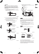
3-5. Shaping the Tubing
● The positions of the refrigerant tubing connections are
shown in the figure below. (The tubing can be routed in
3 directions.) (Fig. 3-20)
* When routing the tubing out through the top or right sides,
cut out the cover of the top panel and cut notches in the side
panel (Refer to fig. 3-3).
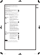
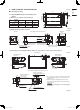
Fig. 3-20
If the tubing is to be routed out
together, use a box cutter or
similar tool to cut out the part
of the cover indicated by
the marked area (Fig. 3-21),
to match the positions of the tubes.
Then draw out the tubing.
Fig. 3-21
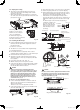
3-6. Installing the Drain Pipe
● Prepare standard PVC pipe for the drain and connect it to
the indoor unit drain pipe with the supplied hose band to
prevent water leaks.
(1) Drain hose connection
● The drain hose is connected below the refrigerant tubing.
(2) Installing the drain hose
●
First insert the drain hose (supplied) to the hose band
(supplied) and then install the drain hose to the unit drain port.
● Insert until the drain hose bumps to the end.
●
Attach the hose band to make the fixed portion 45°upper
gradient according to a vinyl tape (not supplied) of the drain
hose (supplied).
● Hose band screw torque is 30 - 35N · cm.
● Wind the vinyl tape not to blow up the hose band.
● Connect both the drain hose and PVC pipe (VP20 or similar
material, not supplied). Insert until the PVC pipe bumps to
the end and adhere with PVC adhesive.
CAUTION
● Wrap the drain insulator (supplied) between the
connection of the drain hose and tubing not to expose
the copper tubing. Also, wrap the hose band together.
Wrap the hose band with the drain insulator, where
the screw is located facing upward (Fig. 3-23). Then,
tighten the insulator with a vinyl tape not to cause
the detachment. If the tubing parts remain exposed,
condensation may occur.
● Be sure to use the supplied drain hose.
● If other commercially available hose bands are used, the
drain hose may become pinched or wrinkled and there is
danger of water leakage.
Therefore be sure to use the supplied hose bands.
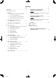
● Connect the drain pipe so that it slopes downward from the
unit to the outside. (Fig. 3-22)
Correct
Incorrect
Downward
slant:
min. 1/100
Upward
slant:
Fig. 3-22
Cover
● Never allow water traps to occur in the course of the piping.
● Insulate any piping inside the room to prevent dripping.
● After the drain piping, pour an appropriate amount of water
into the drain pan through the opening on the side of the air
discharge port. Check the water draining smoothly.
* If the drain hose is routed through the left side, refer to
Fig. 3-20, and follow the procedure above to install the hose.
Reattach the rubber stopper removed earlier onto the right
side.
The rubber stopper can be inserted easily by using a
screwdriver or similar tool to
press the stopper into the
drain port on the main unit.
Press the stopper into the
main unit drain port as far
as it will go.
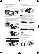
130
26 26
Hose band (supplied)
Do not use adhesive.
Adhere with PVC adhesive.
Hard PVC pipe
(VP20 not supplied)
Drain hose (supplied)
Unit drain port
Unit: mm
Drain insulator (supplied)
(
45°
)
Hose band
Vinyl tape
Drain insulator
Vinyl tape
Drain insulator
Hose band
Fig. 3-23
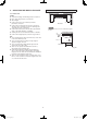
CAUTION
The indoor unit should be slightly tilted downward toward
the drain pipe connection side as shown in fi gure below
so that the wastewater can fl ow smoothly without being
trapped in the middle. (Fig. 3-24)
Ceiling
Approx. 1°
Approx. 2°
Ceiling
Diagonally right down (front view)
(Ex.: Diagonal-right-backwards)
Diagonally backward (side view)
Fig. 3-24
Rubber stopper
Screwdriver
Drain port
PAC-i_T2-type.indb 10PAC-i_T2-type.indb 10 2013/06/11 18:55:352013/06/11 18:55:35