
Installation Instructions

8
3-2. Preparation Before Installation
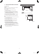
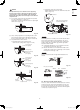
(1) Remove the bracket (for suspending the indoor unit).
Loose the M8 suspension bolts.
Then remove the bracket. (Fig. 3-4)
NOTE
Loosen the M8 suspension bolts and expose the axis of
bolts less than 8 mm.
M4 screw for preventing
bracket from taking off
M8 suspension bolts for
suspending the indoor unit
Bracket
Less than 8 mm
Fig. 3-4
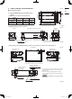
(2) Remove the air-intake grille before suspending the indoor
unit. First, remove 2 attachment screws fixed with the
latches. Open the air-intake grille and hold the claws of
the hinges on both sides. Then remove the air-intake grille
and suspension lug located on the left and right side of the
indoor unit.
1
1
2
Slide
Latch
claws
Screw
Air-intake grille
Fig. 3-5
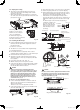
Air-intake grille
Remove
Remove
Fig. 3-6
(3) Remove the side plate to the tubing side.
Rear & upper side
tubing connection
Remove 2 screws.
Slide the side plate in the direction of
the arrow and remove it.
Right side tubing
connection
Do not remove the side plate.
Remove
Screw
Side plate
Fig. 3-7
(4) Remove the center bracket.
When wiring, remove the center bracket if necessary.
When wiring is completed, reinstall the center bracket in its
original position.
Center bracket
Fig. 3-8
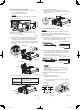
3-3. Suspending the Indoor Unit
NOTE
Since the diagram is made of paper, it may shrink or stretch
slightly because of high temperature or humidity. For this
reason, before drilling the holes maintain the correct dimensions
between the markings.
(1) If the full-scale installation diagram is placed on the ceiling,
the locations of each suspension bolt can be chosen.
Take a pencil and mark the drill holes (Fig. 3-9).
Full-scale installation diagram
Ceiling
Wall
Full-scale installation diagram
Fig. 3-9
(2) If the full-scale installation diagram is bent at right angle
to the ceiling and wall, the locations of the inlet for indoor
tubing and wiring are chosen and the locations of each
suspension bolt can also be chosen.
Take a pencil and mark the drill holes (Fig. 3-10).
Full-scale installation diagram
Ceiling
Wall
Full-scale installation diagram
Fig. 3-10
NOTE
The dimension when the indoor unit is placed tightly
against the wall.
When installing away from the wall, drainage gradient
should be taken into consideration.
(3) Drill holes at the 4 points indicated on the full-scale
diagram.
(4) Depending on the ceiling type:
a) Insert suspension bolts (Fig. 3-11).
or
b) Use existing ceiling supports or construct a suitable
support (Fig. 3-12).
Hole-in-anchor
Hole-in-plug
Suspension bolt (M10 or 3/8”)
(not supplied)
Insert
Ceiling tiles
Ceiling support
Concrete
Fig. 3-11 Fig. 3-12
PAC-i_T2-type.indb 8PAC-i_T2-type.indb 8 2013/06/11 18:55:332013/06/11 18:55:33