
Installation Instructions

9
ENGLISH
WARNING
It is important that you use extreme care in supporting
the indoor unit from the ceiling. Ensure that the ceiling is
strong enough to support the weight of the unit. Before
hanging the ceiling unit, test the strength of each attached
suspension bolt.
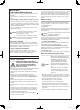
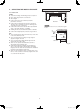
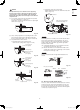
(5) Screw in the suspension bolts, allowing them to protrude
from the ceiling (Figs. 3-11 and 3-12).
The distance of each exposed bolt must be of equal length
within 50 mm. (Fig. 3-13)
Ceiling surface
Within
50 mm
Unit
Bracket
Fig. 3-13
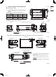
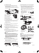
(6) Carry out the preparation for suspending the indoor unit.
The suspension method varies depending on whether
there is a suspended ceiling or not. (Figs. 3-14 and 3-15)
(7) Suspend the indoor unit as follows:
a) Install the bracket to the suspension bolt.
Stick it onto the ceiling surface. (Fig. 3-14~3-16)
Bracket
Suspension bolt
(not supplied)
Ceiling surface
Unit
Washer (supplied)
Double nut
(not supplied)
Fig. 3-14
Suspension bolt
(not supplied)
Washer
(not supplied)
Unit
Washer (supplied)
Double nut
(not supplied)
Fig. 3-15
Suspension bolt
Double nut
(not supplied)
Washer
(supplied)
Ceiling
surface
Approx.
25 mm
Fig. 3-16
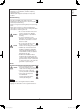
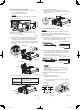
b) Suspend the indoor unit to the bracket.
Tighten the M8 suspension bolts and fix the indoor unit
in place. (Fig. 3-17)
M4 screw for preventing
bracket from taking off
M8 suspension bolts
M8 suspension bolt
Fig. 3-17
NOTE
The ceiling surface is not always level. Confirm that the indoor
unit is evenly suspended. For the installation to be correct,
leave a clearance of about 10 mm between the ceiling panel
and the ceiling surface and fill the gap with an appropriate
insulation or filler material.
(8) If the tubing and wiring are to go towards the rear of the
unit, make holes in the wall. (Fig. 3-18)
(9) Measure the thickness of the wall from the inside to the
outside and cut PVC pipe at a slight angle to fit. Insert the
PVC pipe in the wall. (Fig. 3-19)
NOTE
The hole should be made at a slight downward slant to the
outside.
Indoor
side
Outdoor
side
Fig. 3-18
INSIDE
PVC pipe (not supplied)
Cut at slight angle
PVC pipe
Slight
angle
Wall
OUTSIDE
Fig. 3-19
3-4. Duct for Fresh Air (Field supply)
There is a outside air intake duct connection port (cut out hole)
at the left-rear of the indoor unit for drawing in fresh air. If it is
necessary to draw in fresh air, remove the cover by opening
the hole and connecting the duct to the indoor unit through the
connection port. (Refer to Fig. 3-3)
PAC-i_T2-type.indb 9PAC-i_T2-type.indb 9 2013/06/11 18:55:342013/06/11 18:55:34