ORDER NO.CHM0505009CE DVD / CD Player DVD-K29GCS DL4.1 Mechanism Series Colour (S).......................Silver Type Specifications Power supply: AC220-240 V, 50/60 Hz Power consumption: 11 W lPicture resolution: between 320×240 and 6144×4096 pixels (Sub sampling is 4:2:2 or 4:2:0) Power consumption in standby mode: (9) approx. 1 W Dimensions: 430 (W)×249 (D)×43 (H) mm Mass: 2.
DVD-K29GCS lCD audio: (4) 98 dB Total harmonic distortion: lCD audio: 0.0025 % Digital audio output: Coaxial digital output: Pin jack Pickup Wave length: 662 nm/785 nm Laser power: CLASS 2/CLASS 3A Note: Specifications are subject to change without notice. Mass and dimensions are approximate. Solder: This model uses lead free solder (PbF). CONTENTS Page 1 SAFETY PRECAUTIONS 1.1. GENERAL GUIDELINES Page 4 7.6. Optical Pickup Unit 15 4 7.7.
DVD-K29GCS 13.4. VIDEO BLOCK DIAGRAM 38 16.1. MOTHER P.C.B. 13.5. AUDIO BLOCK DIAGRAM 40 16.2. MOTHER P.C.B. & MODULE P.C.B. ADDRESS INFORMATION 14 INTERCONNECTION SCHEMATIC DIAGRAM & SCHEMATIC 51 52 41 16.3. MODULE P.C.B. (1/2) (COMPONENT SIDE) 53 14.1. INTERCONNECTION SCHEMATIC DIAGRAM 41 16.4. MODULE P.C.B. (2/2) (FOIL SIDE) 54 14.2. SCHEMATIC DIAGRAM NOTES 42 16.5. OPERATION P.C.B. & MIC P.C.B. 55 DIAGRAM NOTES 15 SCHEMATIC DIAGRAM 43 17 EXPLODED VIEWS 15.1.
DVD-K29GCS 1 SAFETY PRECAUTIONS 1.1. GENERAL GUIDELINES 1. When servicing, observe the original lead dress. If a short circuit is found, replace all parts which have been overheated or damaged by the short circuit. 2. After servicing, see to it that all the protective devices such as insulation barriers, insulation papers shields are properly installed. 3. After servicing, make the following leakage current checks to prevent the customer from being exposed to shock hazards. 1.1.1.
DVD-K29GCS Caution Be sure no power is applied to the chassis or circuit, and observe all other safety precautions. 8. Minimize bodily motions when handling unpackaged replacement ES devices. (Otherwise hamless motion such as the brushing together of your clothes fabric or the lifting of your foot from a carpeted floor can generate static electricity (ESD) sufficient to damage an ES device).
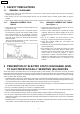
DVD-K29GCS 5 PREVENTION OF STATIC ELECTRICITY DISCHARGE The laser diode in the traverse unit (optical pickup) may brake down due to static electricity of clothes or human body. Use due caution to electrostatic breakdown when servicing and handling the laser diode. 5.1. Grounding for electrostatic breakdown prevention Some devices such as the DVD player use the optical pickup (laser diode) and the optical pickup will be damaged by static electricity in the working environment.
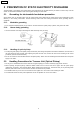
DVD-K29GCS 6 DISASSEMBLING THE CASING AND CHECKING P.C.B.S 6.1. Disassembly Procedure 6.2. Casing Parts and P.C.B.
DVD-K29GCS 6.3. Top Panel 1. Unscrew the screws. 6.5. Mic P.C.B. and Operation P.C.B. 1. Pull out the mic volume knob. 6.4. Front Panel 1. Release the tabs. 2. Unscrew the screws. 2. Release the tabs. 3. Remove the connectors.
DVD-K29GCS 6.6. Module P.C.B. 6.8. Rear Panel 1. Unscrew the screws. 1. Unscrew the screws. 2. Remove the connectors. 2. Release the tabs. 3. Press each tab with the nipper to module PCB vertically. 6.9. Mother P.C.B. and Power SW P.C.B. 1. Unscrew the screws. 6.7. Mechanism Unit 1. Unscrew the screws. 2. Remove the connectors.
DVD-K29GCS 6.10. Service Position 6.10.1. Servicing position of the Module P.C.B. 6.10.2. Servicing position of the Mother P.C.B. 6.10.3.
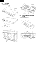
DVD-K29GCS 7 ASSEMBLING AND DISASSEMBLING THE MECHANISM UNIT 7.1. Disassembly Procedure 4. Remove the traverse unit 7.2. Traverse Unit 1. Slide the lever (A) in the arrow direction (to the opposite side) till it stops. 2. Slide the lever (A) further by bending the tab at the right side of the lever A in the right direction. (The right groove opens and the boss becomes seen.) 3. Open the lever (B) to left. (The 2 grooves at the left side open.
DVD-K29GCS 7.3. Tray 1. Slide the guide tray unit while pressing the stopper in the arrow direction, and remove the guide tray unit. 5. Remove the drive arm concave phase from the tray slider and tray. 2. Raise the loading unit. 3. Slide the lever in the arrow direction till it stops and pull the tray out. 1. Insert a part of the tray into the unit sliding over the groove on the mechanical chassis unit. 2.
DVD-K29GCS 4. Remove the belt. 7.4. Loading section 5. Unlock the tab and remove the pulley. 6. Remove the relay gear. 1. Spread the tabs at the both sides and push out the drive arm shaft. 7. Turn the change lever in the arrow direction till it stops. 8. Hook the change lever spring on the change lever project part temporarily. 2. Hook the lock lever spring on the lock lever projection part temporarily. 3. Unlock the tab and remove the lock lever.
DVD-K29GCS 9. Pull the lever (B) in the bottom side to your side and remove the change lever. 10. Remove the drive rack, the sub rack and the drive gear. 7.5. Loading motor P.C.B. 1.
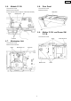
DVD-K29GCS 7.6. 7.6.1. Optical Pickup Unit Cautions to Be Taken in Handling the Optical Pickup Unit The laser diode in the optical pickup unit may be damaged due to electrostatic discharge generating from clothes or human body. Use due caution to electrostatic discharge damage when servicing the laser diode. 1. Do not give a considerable shock to the optical pickup unit as it has an extremely high-precise structure. 2.
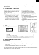
DVD-K29GCS 7.6.2. Procedure for Disassembling the Optical Pickup Unit 1. Move the optical pickup unit in the arrow direction till it stops. 6. Lift the optical pickup unit with the shaft. 2. Unscrew the screws. 7. Remove the optical pickup unit. 3. Remove the drive rack. 4. Unscrew the screw 8. Pull the shaft and the rubber out. 5. Slide the shaft in the arrow direction.
DVD-K29GCS 1. Pass the intermediate FPC through the frame hole. 2. Align the guide section of the optical pickup unit with the rail. 2. Remove the cover while lifting the inner gear. 3. Install the shaft top to the holder. 3. Remove the solders. 4. The intermediate FFC is fixed as shown below. 4. Remove the traverse motor. 7.7. Traverse Motor 1. Unscrew the screws.
DVD-K29GCS 18
DVD-K29GCS 8 Self-Diagnosis Function and Service Modes 8.1. Optical Pickup Breakdown Diagnosis The optical pickup self-diagnosis function and tilt adjustment check function have been included in this unit. When repairing, use the following procedure for effective Self-diagnosis and tilt adjustment.Be sure to use the self-diagnosis function before replacing the optical pickup when "NO DISC" is displayed.
DVD-K29GCS 8.2. Service Mode Table 1 The service modes can be activated by pressing various button combination on the player and remote control unit. Player buttons PAUSE + OPEN/CLOSE Remote control unit buttons 0 5 6 7 9 FUNCTION PAUSE PAUSE QUICK OSD OPEN/CLOSE 8.3. Application Displaying the UHF display F_ _ _ Note Refer to section 8.3. SelfDiagnosis Function (UHF Display). Jitter check, tilt adjustment Refer to section 10.4.
DVD-K29GCS Error Code F611 F612 F630 F631 F632 F103 Error Content 6626 QCODE don’t read Error No CRC OK for a specific time No reply to KEY DET enquiry CPPM KEY DET is not available till the FILE terminal CPPM KEY DET is not available Disc code Illegal highlight Position Additional error explanation Access failure to seek address in CD series Defect 1 DV2 (IC8001) DV2 (IC8001) Defect 2 (CPPM file system is unreadable caused by scratches) DISC CPPM (*1) Been revoked or falsified DISC EEPROM (IC8
DVD-K29GCS 8.5. Service mode table 2 Pressing various button combinations on the player and remote control unit can activate the service modes.
DVD-K29GCS 23
DVD-K29GCS 8.6. Sales demonstration lock function This function prevents discs from being lost when the unit is used for sales demonstrations by disabling the disc eject function. "LOC" is displayed on the unit, and ordinary operation is disabled. 8.6.1. Setting The sales demonstration lock is set by simultaneously pressing STOP button on the player and POWER button on the remote control unit for 1 second or longer. 8.6.2.
DVD-K29GCS 9 Service Precautions 9.1. Recovery after the dvd player is repaired · When FROM or module P.C.B. is replaced, carry out the recovery processing to optimize the drive. Playback the recovery disk to process the recovery automatically. · Recovery disc [Product number: RFKZD03R005] (RFKZD03R004 can not be recovered as a partial item. So use the new recovery disc, RFKZD03R005.) · Performing recovery 1. Load the recovery disc RFKZD03R005 on to the player and run it. 2.
DVD-K29GCS 10 ADJUSTMENT PROCEDURES 10.1. Service Tools and Equipment Application Tilt adjustment Name Number DVDT-S15 or DVDT-S01 DVD test disc TORX screw driver (T6) Inspection Others Confirmation Extension cable (module P.C.B. to mother P.C.B.) Extension cable (module P.C.B. to mother P.C.B.) Hanarl Grease Drysurf CD test disc VCD test disc Recovery disc Available on sales route.
DVD-K29GCS 10.4. Optical adjustment 10.4.1. Optical pickup tilt adjustment Measurement point Adjustment point Tangential adjustment screw Tilt adjustment screw Measuring equipment None (Main unit display for servicing is used.) Mode Disc T01 (inner periphery) play DVDT-S15 or DVDT-S01 T30 (central periphery) play T43 (outer periphery) play Adjustment value Adjust to the minimum jitter value. 10.4.1.1.
DVD-K29GCS 10.4.1.4. Procedure for screw lock It is also possible to perform screw lock on the head of an adjustment screw after an adjustment end using an injector etc. from the hole at the bottom of a product (hole of bottom chassis), without decomposing. Please perform a screw lock in which by the side of the tip or head of an adjustment screw. 1. After adjustment, remove top panel. 2.
DVD-K29GCS 11 Abbreviations INITIAL/LOGO A A0~UP ACLK AD0~UP ADATA ALE AMUTE AREQ ARF ASI ASO ASYNC B BCK BCKIN BDO BLKCK BOTTOM BYP BYTCK C CAV CBDO CD CDSCK CDSRDATA CDRF CDV CHNDATA CKSL CLV COFTR CPA CPCS CPDT CPUADR CPUADT CPUIRQ CPRD CPWR CS CSYNCIN CSYNCOUT D DACCK DEEMP DEMPH DIG0~UP DIN DMSRCK DMUTE DO DOUT0~UP DRF DRPOUT DREQ DRESP DSC DSLF DVD ABBREVIATIONS ADDRESS AUDIO CLOCK ADDRESS BUS AUDIO PES PACKET DATA ADDRESS LATCH ENABLE AUDIO MUTE AUDIO PES PACKET REQUEST AUDIO RF SERVO AMP INVERTED
DVD-K29GCS INITIAL/LOGO R RE RFENV RFO RS RSEL RST RSV S SBI0, 1 SBO0 SBT0, 1 SCK SCKR SCL SCLK SDA SEG0~UP SELCLK SEN SIN1, 2 SOUT1, 2 SPDI SPDO SPEN SPRCLK SPWCLK SQCK SQCX SRDATA SRMADR SRMDT0~7 SS STAT STCLK STD0~UP STENABLE STSEL STVALID SUBC SBCK SUBQ SYSCLK T TE TIBAL TID TIN TIP TIS TPSN TPSO TPSP TRCRS TRON TRSON ABBREVIATIONS READ ENABLE RF ENVELOPE RF PHASE DIFFERENCE OUTPUT (CD-ROM) REGISTER SELECT RF POLARITY SELECT RESET RESERVE SERIAL DATA INPUT SERIAL DATA OUTPUT SERIAL CLOCK SERIAL DATA C
DVD-K29GCS 12 VOLTAGE CHART Note: · Circuit voltage and waveform described herein shall be regarded as reference information when probing defect point, because it may differ from an actual measuring value due to difference of Measuring instrument and its measuringcondition and product itself. 12.1. MOTHER P.C.B. Ref No. MODE PLAY STOP Ref No. MODE PLAY STOP Ref No. MODE PLAY STOP Ref No. MODE PLAY STOP Ref No. MODE PLAY STOP Ref No. MODE PLAY STOP Ref No. MODE PLAY STOP Ref No. MODE PLAY STOP Ref No.
DVD-K29GCS 12.2. MODULE P.C.B. Ref No. MODE PLAY STOP Ref No. MODE PLAY STOP Ref No. MODE PLAY STOP Ref No. MODE PLAY STOP Ref No. MODE PLAY STOP Ref No. MODE PLAY STOP Ref No. MODE PLAY STOP Ref No. MODE PLAY STOP Ref No. MODE PLAY STOP Ref No. MODE PLAY STOP Ref No. MODE PLAY STOP Ref No. MODE PLAY STOP Ref No. MODE PLAY STOP Ref No. MODE PLAY STOP Ref No. MODE PLAY STOP Ref No. MODE PLAY STOP Ref No. MODE PLAY STOP Ref No. MODE PLAY STOP Ref No. MODE PLAY STOP Ref No. MODE PLAY STOP Ref No.
DVD-K29GCS Ref No. MODE PLAY STOP Ref No. MODE PLAY STOP Ref No. MODE PLAY STOP Ref No. MODE PLAY STOP Ref No. MODE PLAY STOP Ref No. MODE PLAY STOP Ref No. MODE PLAY STOP IC8611 4 5 0 3.3 0 3.3 1 0 0 2 0 0 3 0 0 1 1.0 2 0.3 3 0.6 4 2.4 21 0 22 0 23 0 41 0.6 43 0.6 E 5.0 5.0 42 0.6 Q8550 C 5.0 5.1 Q8562 C 0.1 0.1 1 0 0 2 0 0 E 5.0 5.1 6 3.3 3.3 7 0 0 8 3.3 3.3 5 0 6 0 7 3.3 8 3.3 9 0 24 0 25 3.3 26 3.3 27 0 28 3.3 29 0.6 44 0.6 45 0.6 47 3.3 48 0 E 0.
DVD-K29GCS 34
DVD-K29GCS 13 BLOCK DIAGRAM Note: Circuit voltage and waveform described herein shall be regarded as reference information when probing defect point, because it may differ from an actual measuring value due to difference of Measuring instrument and its measuringcondition and product itself. 13.1. OVERALL BLOCK DIAGRAM MECHANISM UNIT MODULE P.C.B. MIC P.C.B.
DVD-K29GCS 13.2. POWER SUPPLY BLOCK DIAGRAM PRIMARY CIRCUIT SECONDARY CIRCUIT IC6001 L1001 D1011,C1011 (OPERATION CPU) T1021 FL AC SOCKET P1001 VA1002 SURGE KILLER 10 LINE FILTER RECTIFIER F1001 NSW+9V NSW-12V VCC VEE AUDIO OP AMPS DGT8 40 DGT11 37 POWER TRANSFORMER Q1125 11 REG. D+1.2V SEG0 41 Q1126 SEG15 56 SWITCH A+5V Q1115 12 D+5V REG. QR1115 N.POWER OFF L SWITCH 63 N.P.OFF L IC1151 IC1021 CONSTANT VOLTAGE CONTROL (REG.M+9V) 2 ON/OFF 1 IN OUT 3 15 16 M+9V IC1195 REG.
DVD-K29GCS 13.3.
DVD-K29GCS 13.4.
DVD-K29GCS VIDEO MAIN SIGNAL IC3501 (VIDEO DRIVE) BIAS 2 A CIN 4dB LPF 2dB 75 DRIVER 8dB 75 DRIVER 2dB 75 DRIVER COUT 6.75MHz -6dB + CVBS OUT 16 JK4401 VIDEO OUT 15 CLAMP 4 B YIN 4dB LPF YOUT 14 JK4401 S-VIDEO OUT 6.75MHz MUTE BIAS 1.4V MUTE JK4401 CLAMP C 6 CYIN 4dB LPF 2dB 75 DRIVER 2dB 75 DRIVER 2dB 75 DRIVER CYOUT 13 Y 12 PB 11 PR 13.5MHz BIAS 8 D CBIN 4dB LPF CBOUT 6.75MHz BIAS E 9 CRIN 4dB LPF CROUT 6.75MHz IC3501-11 1.2Vp-p(20usec./div.
DVD-K29GCS 13.5. AUDIO BLOCK DIAGRAM IC8001 (DV2) DACCK 163 MCLK 1 (AUDIO D/A CONVERTER) SMUTE/CSM ACKS/C CLK DIF0/CDTI STBDAC 53 SBT3 56 STO3 57 LRCK LRCK 169 BICK SRCK 170 SDTI ADOUT3 171 6 7 8 3 DE-EMPHASIS CONTROL µP INTERFACE 4 2 AUDIO MAIN SIGNAL IC8421-10,11 0.44Vp-p(0.5msec./div.
DVD-K29GCS 14 INTERCONNECTION SCHEMATIC DIAGRAM & SCHEMATIC DIAGRAM NOTES 14.1. INTERCONNECTION SCHEMATIC DIAGRAM MIC P.C.B. OPTICAL PICK UP UNIT E T+ F+ FTHFM TA(DVD) TB(DVD) TD(DVD) TC(DVD) FE2(DVD/CD) FE1(DVD/CD) GND RF VREF2(RF-) PIN(DVD) LDCD LDGND LDDVD GND(OEIC) VREF1 VCC SUB2 SUB1 PIN(CD) SUBSEL GND(VRCD) DGND D+5V DGND A+5V AGND D+1.
DVD-K29GCS 14.2. SCHEMATIC DIAGRAM NOTES This schematic diagram may be modified at any time with the development of new technology. Important safety notice: Components identified by mark have special characteristics important for safety. Furthermore, special parts which have purpose of fire-retardant (resistors), high-quality sound (capacitors), low-noise (resistors), etc. are used. When replacing any of components, be sure to use only manufacture´s specified parts shown in theparts list.
DVD-K29GCS 15 SCHEMATIC DIAGRAM 15.1. POWER SUPPLY SECTION (MOTHER P.C.B.
DVD-K29GCS 15.2. FRONT & AV OUT SECTION (MOTHER P.C.B. (2/2)) SCHEMATIC DIAGRAM A B DP6081 A2BA00000217 P14 P13 4G 3G P12 P11 P10 3G P9 2G P8 P7 P6 2G P5 1G P4 P3 1G P2 P1 1G F- F- Q6085 B1ABGC000011 4G A1 P15 C3825 6V1000 P16 RESET L3801 G0C680JA0019 4G PO B C D E F+ A+5V D+5V M+9V D+1.
DVD-K29GCS A A A44 B A45 A52 B C D E B C C4415 25V47 R4356 15K C4314 0.1 R4423 47K C4337 82P C4323 25V220 8 VCC 7 6 5 + IC4301 C0ABBB000118 + - 1 2 (AMP) 3 VEE 4 C4414 25V47 C4336 82P R4355 15K C4315 0.1 R4422 47K K4312 A15 A30 A17 A16 R4331 9.1K R4332 9.1K R4312 22K R4311 100K R4310 100K Q4947 B1ABCF000138 Q4948 B1ABCF000138 (MUTE) (MUTE) R4947 820 R4948 820 R4949 10K R4414 0 Q4949 UNR221100L R4415 0 (MUTE CTL.) 6 5 4 QR4305 XN0431100L R4402 8.
DVD-K29GCS A VIDEO MAIN SIGNAL B C AUDIO MAIN SIGNAL B JK4401 K2YZ19000001 ZA4701 RMCC0001 R3535 75 C3513 6V1000 LB3535 J0JBC0000117 17 PB 16 PR 15 VGND 14 Y 13 V 12 VGND 4 METAL GND 11 CK 10 CK GND 7 Y(S) C3512 6V1000 ZA4751 K4CZ01000027 C3514 6V1000 R4752 1K LB3532 J0JBC0000117 LB3531 J0JBC0000117 R3537 10K Q4751 B1ABCF000138 C4751 25V47 LB3533 J0JBC0000117 R3531 75 C3517 0.
DVD-K29GCS 15.3. MODULE SCHEMATIC DIAGRAM A A15 B ERJ2GE0R00X ERJ2GE0R00X ERJ2GEJ101X ERJ2GEJ101X ERJ2GEJ101X A1 A2 A3 K8102 0 CL8234 17 16 15 VO5- 18 VO5+ 19 VO4- 20 VO4+ 21 PGND 30 PVCC12 22 PVCC45 23 VIN4 OPIN- 24 GND 25 VIN5 26 OPIN+ 27 1 29 11 12 13 14 5 NC 10 6 CONT 9 7 NC 8 8 VIN 7 VO1+ 6 VO1- 5 VO2+ 4 VO2- 3 VO3+ 2 VO3- 1 PVCC3 (MOTOR DRIVE) IC8111 C0CBCBD00018 E17 E18 (REG.D+3.3V) GND CN C8505 220P NC C8504 0.1 VO C8503 0.
DVD-K29GCS A A A20 B C LB8001 LB8002 B J0JHC0000097 J0JHC0000097 D C8002 4V330 C8001 6V100 C8027 0.1 C8028 1 A21 A23 A24 A25 C8026 1 C8025 0.1 C8024 2200P C8023 1 C8022 0.1 C8021 0.1 C8020 0.1 C8019 1 C8018 0.
DVD-K29GCS A20 A VIDEO MAIN SIGNAL B C AUDIO MAIN SIGNAL RF SIGNAL D C8611 0.1 C8601 0.1 R8601 1K 2 4 RX8611 4.
DVD-K29GCS 15.4. MIC SCHEMATIC DIAGRAM AUDIO MAIN SIGNAL J4671 K2HB102J0038 1 D 2 LB4673 J0JCC0000120 R4677 1K C4681 50V1 R4557 1.2K R4680 220K 3 MIC 1 R4678 22K 4 C4678 0.001 C4691 0.082 R4567 1.
DVD-K29GCS 16 PRINT CIRCUIT BOARD 16.1. MOTHER P.C.B. MOTHER P.C.B. LOADING MOTOR P.C.B. F E D C POWER SW P.C.B. B A DVD-K29GCS MOTHER P.C.B.(VEP76116C) POWER SW P.C.B.(VEP76117A) LOADING MOTOR P.C.B.
DVD-K29GCS 16.2. MOTHER P.C.B. & MODULE P.C.B. ADDRESS INFORMATION MOTHER P.C.B.
DVD-K29GCS 16.3. MODULE P.C.B. (1/2) (COMPONENT SIDE) MODULE P.C.B. (1/2) F E D C B A (COMPONENT SIDE) 1 DVD-K29GCS MODULE P.C.B.
DVD-K29GCS 16.4. MODULE P.C.B. (2/2) (FOIL SIDE) MODULE P.C.B. (2/2) F E D C B A (FOIL SIDE) 1 DVD-K29GCS MODULE P.C.B.
DVD-K29GCS 16.5. OPERATION P.C.B. & MIC P.C.B. MIC P.C.B. Inntegrated Circuit Connectors IC4671 B-1 P4601 IC4691 B-4 P4602 ADDRESS INFORMATION C-3 C-3 MIC P.C.B. C OPERATION P.C.B. B B A A DVD-K29GCS OPERATION P.C.B. (REP70123A) 1 2 3 4 DVD-K29GCS MIC P.C.B.
DVD-K29GCS 56
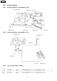
DVD-K29GCS 17 EXPLODED VIEWS 17.1.
DVD-K29GCS 17.2.
DVD-K29GCS 17.3.
DVD-K29GCS 18 REPLACEMENT PARTS LIST Notes: *Important safety notice: Components identified by mark characteristics important for safety. have special Furthermore, special parts which have purposes of fireretardant (resistors), high-quality sound (capacitors), lownoise (resistors), etc. are used. When replacing any of components, be sure to use only manufacture’s specified parts shown in the parts list. *Warning: This product uses a laser diode. Refer to caution statements.
DVD-K29GCS Ref. No. C1101 C1102 C1110 C1111 C1112 C1115 C1116 C1117 C1121 C1122 C1125 C1126 C1127 C1141 C1151 C1153 C1154 C1155 C1171 C1195 C1196 C1197 C3505 C3506 C3507 C350811 C351216 C3517 C3518 C3519,2 0 C3825 C4050 C4309,1 0 C431315 C4323,2 4 C4336,3 7 C4414,1 5 C4423 C4427 C4431 C4432 C4591 C4675 C4677 C4678 C4679 C4680,8 1 C4682,8 3 C4691 C4692 C4693 C4694 C4695,9 6 C4703 C4751,5 2 C4781 C6001 C6002 C6003 C6005 C6006 C6040 C6050 Part No.
DVD-K29GCS Ref. No. C8422,2 3 C8425 C8426 C8501 C850204 C8505 C8506 C8550 C8551 C8552 C8553 C8554 C8561 C8562 C8563 C8564 C8601 C8611 C8621 C8622 C8651,5 2 Part No. F1G1C104A083 Part Name & Description 16V 0.1U Pcs F2G0J330A083 F1G1C104A083 ECJ3YB1A106K F1G1C104A083 6.3V 33U 16V 0.1U 10V 10U 16V 0.
DVD-K29GCS Ref. Part No. No.
DVD-K29GCS Ref. No. R6002,0 3 R6006 R6008 R6009 R6011 R6022 R6023 R6024 R6025 R6026 R6040 R6050 R6060 R6071 R6072 R6081 R6085 R6086 R6101 R6151 R6161 R6171 R8011 R8021,2 2 R8023 R8041 R8201 R8231 R8233 R8235,3 6 R8241 R8242 R8243 R8254 R8255 R8261 R8262 R8263 R8264 R8265 R8311 R8312 R8313 R8314 R8315 R8321 R8322 R8325 R8326 R8331 R8332 R8335 R8341 R8401 R8402 R8404 R8420 R8421 R8431 R8501 R8505 R8506 R8550 R8551 R8552,5 3 R8554 R8555 R8556 R8557 R8558 Part No.