Network Camera Network Operating Instructions Model No. LOCK WV-NS202A OPEN Before attempting to connect or operate this product, please read these instructions carefully and save this manual for future use.
CONTENTS Preface ............................................................................................................................ 3 About these operating instructions .............................................................................. 3 Trademarks and registered trademarks ...................................................................... 3 Viewer software ...........................................................................................................
Preface About these operating instructions There are 2 sets of operating instructions for the WV-NS202A as follows. • Installation Guide • Network operating instructions These network operating instructions contain descriptions of how to operate this product using a PC via a network and of how to configure the settings. Refer to the installation guide for descriptions of how to install this product and of how to connect to a network. Adobe® Reader is required to read PDF.
Monitor images on a PC The following are descriptions of how to monitor images from the camera on a PC. Monitor images from a single camera Step 1 Start up the web browser. Step 2 Enter the IP address designated using the Panasonic IP setup software in the address box of the browser. (Example: http://192.168.0.10) Important: • When the HTTP port number is changed from "80", enter "http://IP address of the camera + : (colon) + port number" in the address box of the browser, for example, "http://192.168.0.
About the "Live" page !7 Full screen button !6 Alarm occurrence indication button !8 One shot button !5 Camera title !9 Mic input button @0 Audio output button q [Setup] button @1 SD recording status indicator w [Live] button e Multi-screen buttons r Image type buttons @2 Main area t Image capture size buttons y AUX buttons !3 BRIGHTNESS buttons u [SD] button !4 PRESET i [List] button o Zoom buttons !1 AUTO MODE !2 Control pad/buttons !0 Focus buttons q [Setup] button (*1) Click this button
u [SD] button (manual SD recording button) (*2) This button will be displayed only when "Manual" is selected for "Save trigger" on the setup menu. (☞ page 27) Click this button to manually record images on the SD memory card. Refer to page 10 for descriptions of how to manually record images on the SD memory card. i [List] button (*1) This button will become available only when "ON" is selected for "Save logs" on the setup menu (☞ page 31).
• • • • original position (where the camera was when "360° map-shot" or "Preset map-shot" was carried out). When "360 map-shot" is carried out while the camera is moving (panning/tilting), images captured while panning/tilting may be displayed as the thumbnail display. In this case, stop the current operation and carry out "360 map-shot" again.
!9 Mic input button (*3) Turns on/off the audio reception (hear audio from the camera on a PC). This button will be displayed only when "Mic input" or "Interactive" is selected for "Audio mode" on the setup menu. (☞ page 49) When this button is clicked, the button will turn into the button and audio from the camera will not be heard. Audio volume can be adjusted (Low/Middle/High) by moving the volume cursor .
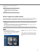
Refer to page 63 for further information about the access level. Note: When operated by a lower access level user, images displayed on the screen may be changed temporarily. This does not affect operation of the camera. Monitor images from multiple cameras Images from multiple cameras can be displayed on a multi-screen. Images from 4 cameras (up to 16 cameras) can be displayed simultaneously. To display images on a multi-screen, it is necessary to register cameras in advance.
Record images on the SD memory card manually Images displayed on the "Live" page can be recorded on the SD memory card manually. This button is operable only when "Manual" is selected for "Save trigger" on the setup menu. (☞ page 27) Images recorded on the SD memory card can be copied onto the PC. (☞ page 29) Step 1 Display the "Live" page. (☞ page 4) Step 4 Click the [STOP] button to stop saving images on the SD memory card. Step 5 Click the [CLOSE] button to close the window.
Action at an alarm occurrence The alarm action will be performed when the following alarms occur. Alarm type Terminal alarm: When connecting an alarm device such as a sensor to the EXT I/O connector 1-3 on the rear of the camera, the alarm action (camera action at an alarm occurrence) will be performed when the connected alarm device is activated. Alarm action to be performed differs depending on the settings configured in the "Camera motion on alarm" section of the [Alarm] tab.
Transmit images onto an FTP server Images can be transmitted to an FTP server. By configuring the following settings, transmission of images captured at an alarm occurrence or captured at a designated interval to an FTP server will become available. Important: • When using this function, set the user name and the password to access the FTP server to restrict users who can log into the FTP server.
Save images on the SD memory card when images fail to transmit using the FTP periodic transmission function Images that have failed to transmit using the FTP periodic transmission can be saved automatically on the SD memory card. Images saved on the SD memory card can be obtained from the [SD memory card] tab of the "Basic setup" page.
Display the log list The following logs can be displayed in list form. • Alarm log: Logs of the alarm occurrences such as time and date of the alarm occurrences and the alarm type will be displayed. • Manual log: Logs filed when images have been recorded on the SD memory card will be displayed. • FTP error log: Logs filed when the FTP periodic transmission function has failed will be displayed.
Log list displayed in the log list window [Number of the listed logs] Total number of the logs of the selected log type and a number of the log being displayed on the top of the log list will be displayed. Note: Enter the desired log number and press the [Enter] key on the keyboard. The log of the designated number will be displayed on the top of the log list. [TOP] button Click this button to display the log listed on the top of the currently displayed log list.
[Download] button Click this button to download all logs of the selected log list as a file onto the PC. [CLOSE] button Click this button to close the log list window.
Playback of images saved on the SD memory card When clicking a time and date listed on the log list window, the "live" page will turn to the "playback" page. When images associated with the clicked time and date are on the SD memory card, the first image of them will be displayed. Important: • Refresh interval of images may become slow during playback or download. • When many images are saved on the SD memory card, it may take time to display images on the "playback" page.
[STOP] button Playback will stop and the "playback" window will turn to the "live" page. [NEXT IMAGE] button The next frame will be displayed and paused when this button is clicked during playback. Each time this button is clicked during pausing, the frame next to the currently displayed frame will be displayed. Note: When the mouse button is being held while placing the mouse pointer on this button, the displayed image number will be incremented.
About the network security of the camera Equipped security functions The following security functions are featured in this camera. q Access restrictions by the host authentication and the user authentication It is possible to restrict users from accessing the camera by setting the host authentication and/or the user authentication to "ON". (☞ pages 63 and 64) w Access restrictions by changing the HTTP port It is possible to prevent illegal access such as port scanning, etc. by changing the HTTP port number.
Display the setup menu and configure the settings of the camera using a PC The settings of the camera can be configured on the setup menu. The setup menu is only operable by users whose access level is "1. Administrator". How to display the setup menu Step 1 Display the "Live" page. (☞ page 4) Step 2 Click the [Setup] button on the "Live" page. → The window with the user name and password entry fields will be displayed. Step 3 Click the [OK] button after entering the user name and the password.
How to operate the setup menu Important: When there are two or more [SET] buttons on the page, click the respective button to the edited setting item. A Menu buttons Setup page A-1 B Step 1 Click the desired button in the frame on the left of the window to display the respective setup menu. When there are tabs at the top of the setup page displayed in the frame on the right of the window, click the desired tab to display and configure the setting items relating to the name of the tab.
About the setup menu window !2 Status display area q [Live] button w [Basic setup] button e [Camera setup] button r [Multi-screen setup] button !3 Setup page t [Alarm setup] button y [Authentication setup] button u [Server setup] button i [Network setup] button o [Schedule setup] button !0 [Maintenance] button !1 [Help] button q [Live] button Click this button to display the "Live" page. w [Basic setup] button Click this button to display the "Basic setup" page.
i [Network setup] button Click this button to display the "Network setup" page. The network settings and the settings relating to DDNS (Dynamic DNS), SNMP (Simple Network Management Protocol) and the FTP (File Transfer Protocol) periodic transmission function can be configured on the "Network setup" page. Refer to page 67 for further information. o [Schedule setup] button The "Schedule" page will be displayed.
Configure the basic settings of the camera [Basic setup] The basic settings such as time and date and camera name, and the settings relating to the NTP server and the SD memory card can be configured on the "Basic setup" page. The "Basic setup" page has 4 tabs; the [Basic] tab, the [NTP] tab, the [SD memory card] tab and the [LOG] tab. Configure the basic settings [Basic] Click the [Basic] tab on the "Basic setup" page.
• SD memory card error LED: This LED will light when the SD memory card is unavailable to save images. • Power LED: This LED will light when the power is on. [OSD Position] Select a position where time and date, camera title, preset ID, panning/tilting angle, zoom ratio are to be displayed on the "Live" page. Upper left: The above information will be displayed at the upper left corner of the main area on the "Live" page.
Configure the settings relating to the NTP server [NTP] Click the [NTP] tab on the "Basic setup" page. (☞ pages 20 and 21: How to display/operate the setup menu) The settings relating to the NTP server such as the NTP server address, port number, etc. can be configured on this page. [NTP port] Enter a port number to be used for the NTP server.
Configure the settings relating to the SD memory card [SD memory card] Click the [SD memory card] tab on the "Basic setup" page. (☞ pages 20 and 21: How to display/operate the setup menu) The settings relating to the SD memory card can be configured on this page. and 2% when "50%" is selected. Notification may not always be made at the very moment when the remaining space of the SD memory card has reached each value. [Save trigger] Select a trigger to save images on the SD memory card from the following.
File name: ["Entered file name" + "Time and date (year/month/day/hour/minute/second)"] + "Serial number" Number of characters that can be entered for the file name: 1 - 8 characters Note: When "FTP error" is selected for "Save trigger", the file name entered for "File name" on the [FTP] tab of the "Network setup" page will be used for the file name of the image saved on the SD memory card. [Frame rate] • Frame per second Select an image save interval from the following. 0.1 fps/0.2 fps/0.33 fps/0.
• Do not turn off the power of the camera during the process of formatting. • After formatting the SD memory card, the available size may be smaller than the total size since the default directory is automatically created in the SD memory card. • Compatible SD memory card is as follows. SD memory card manufactured by Panasonic (64 MB, 128 MB, 256 MB, 512 MB, 1 GB, 2GB) • Use the SD memory card without changing the default condition, or use it after formatting in conformity with the SD specification.
Possible number of images that can be saved on the SD memory card (as indications) Important: The numbers on the following table are just indications. They are not actual numbers of images that can be saved on the SD memory card. Numbers will differ according to photographic subject, settings relating to the SD memory card, etc. Image capture size: VGA Size of SD memory card Image quality 0 (Super fine) 1 (Fine) 2 3 4 2 GB Approx. 10 000 pics Approx. 14 000 pics Approx. 16 000 pics Approx.
Configure the settings relating to the logs [LOG] Click the [LOG] tab on the "Basic setup" page.(☞ pages 20 and 21: How to display/operate the setup menu) Important: When "Without time and date" is selected for "File name" on the [FTP] tab on the "Network setup" page (☞ page 72), FTP error log and associated images will not be saved. To save them, select "With time and date". ■ Alarm [Save logs] Select "ON" or "OFF" to determine whether to save the alarm logs.
How the logs and images are saved depending on the settings for "Alarm" [LOG] tab [SD memory card] tab Alarm: Save logs SD memory card Save trigger Logs and associated images Logs: Alarm input Use Up to 5 000 logs will be kept. When more than 5 000 logs are filed, the older logs will be overwritten by the newer logs. In this case, the oldest log is the first to be overwritten. Images: Images associated with the logs will be saved.
How the logs and images are saved depending on the settings for "Manual" [LOG] tab Manual: Save logs [SD memory card] tab SD memory Save trigger Overwrite card Logs and associated images Logs: ON Manual Use Images: Images associated with the logs will be saved. When available capacity of the SD memory card ran out, the older images will be overwritten by the newer images.
[LOG] tab Manual: Save logs [SD memory card] tab SD memory Save trigger Overwrite card Logs and associated images Logs: OFF Not use – Logs will not be saved. – Images: Images will not be saved. How the logs and images are saved depending on the settings for "FTP error" [LOG] tab FTP error: Save logs [SD memory card] tab SD memory card Logs and associated images Save trigger Logs: FTP error Images: Images will be saved.
Configure the settings relating to images and audio [Camera setup] The settings relating to JPEG/MPEG-4 images and camera operations such as the settings of image quality, preset positions, audio, etc. can be configured on this page. The "Camera setup" page has 4 tabs; the [JPEG/MPEG-4] tab, the [Cam Function] tab, the [Image/Position] tab and the [Audio] tab. Configure the settings relating to JPEG/MPEG-4 images [JPEG/MPEG-4] Click the [JPEG/MPEG-4] tab on the "Camera setup" page.
■ MPEG-4 setup Click the [JPEG/MPEG-4] tab on the "Camera setup" page. (☞ pages 20 and 21: How to display/operate the setup menu) Configure the settings relating to MPEG-4 image such as "Max bit rate (per 1 client)", "Image capture size", "Image quality", etc. in this section. Refer to page 35 for further information about the settings relating to JPEG images. Refer to page 89 for how to configure settings to transmit MPEG-4 images via the Internet.
Multicast: No concurrent access limitation for a camera. Refer to page 4 for further information about the maximum concurrent access number. Default: Unicast port (AUTO) [Unicast port1 (Image)] Enter the unicast port number (used to transmit images from the camera). Available port number: 1024 - 50000 (Only even numbers are available.) Default: 32004 [Unicast port2 (Audio)] Enter the unicast port number (used to transmit audio from the camera).
Configure the settings relating to the camera title and the camera operations [Cam Function] Click the [Cam Function] tab on the "Camera setup" page. (☞ pages 20 and 21: How to display/operate the setup menu) Configure the settings relating to camera title and the camera operations on this page. [Camera title on screen] Select "ON" or "OFF" to determine whether or not to display the camera title on images. Default: OFF [Camera title on screen (0-9, A-Z)] Enter the camera title to be displayed on images.
[Upside-down] Select "ON (desktop)" or "OFF (ceiling)" to determine how the camera is to be installed. ON (desktop): Select this when the camera is to be installed with the dome side up. OFF (ceiling): Select this when the camera is to be installed with the dome side down. Default: OFF (ceiling) [EL-ZOOM] Select "ON" or "OFF" to determine whether or not to use the electronic zoom. ON (Max X10): Images can be zoomed in on with the optical zoom (1x - 22 x) and the electronic zoom (23x – 220x).
Configure the settings relating to images and the preset positions [Image/Position] Click the [Image/Position] tab on the "Camera setup" page. (☞ pages 20 and 21: How to display/operate the setup menu) When the [SETUP>>] button of each setting item is clicked, the detailed settings menu will be displayed in a newly opened window. The detailed settings can be configured while monitoring images displayed on the [Image/Position] tab.
Configure the settings relating to image quality ("Image Adjust" setup menu) Click the [SETUP>>] button of "Image Adjust" on the [Image/Position] tab of the "Camera setup" page. (☞ page 40) The settings relating to image quality can be configured with the setup menu displayed in a newly displayed window. When the values are changed, the changed values will be applied immediately to the currently displayed image on the [Image/Position] tab.
[Mask area] When "OFF" is selected for "Super Dynamic 3", it is possible to compensate for backlight by masking the brighter area. Refer to page 44 for descriptions of how to mask. [Shutter] Select the shutter speed from the following. AUTO: Provides clearer images of bright objects outdoors since the shutter speed is adjusted automatically. Flickering caused by fluorescent lamps can also be compensated. OFF: Fixed at 1/60 sec 1/100: Recommended when flickering caused by fluorescent lamp appears frequently.
• After selecting "AWC", click the [ADJUST] button. It will take for around 7 seconds to complete the white balance adjustment. [CLOSE] button Click this button to close the "Image Adjust" setup menu. [Red Gain] Adjust the red color of images. When the cursor is moved in the "+" direction, the red color will become thicker. When the cursor is moved in the "–" direction, the red color will be thinner. Click the [RESET] button to reset the color to the default. [Blue Gain] Adjust the blue color of images.
Set mask areas When "OFF" is selected for "Super Dynamic 3", it is possible to compensate for backlight by masking brighter areas. Step 1 Display the setup menu of "Image Adjust". (☞ page 41) Step 2 Click the [START] button of "Mask area". → Borders will appear and the image displayed on the [Image/Position] tab will be divided into 48 (6x8). Step 3 Click the divided areas to be masked. → The clicked areas will be masked and will become white. To cancel masking, click the area again.
Configure the settings relating to the preset positions ("Preset No." setup menu) Click the [SETUP>>] button of "Preset Position" on the [Image/Position] tab of the "Camera setup" page. (☞ page 40) It is possible to register, edit and delete the preset positions on this page. When the focus, brightness, zoom factor are adjusted, the adjustment will be applied immediately to the currently displayed image on the [Image/Position] tab.
[Preset No.] [SET] button: When the position of the camera is determined using the [ZOOM] buttons, the [FOCUS] buttons, the [BRIGHTNESS] buttons and the control pad/buttons, click this button after selecting the desired preset position number (1 - 64) from the pulldown menu. The determined position will be newly registered as the preset position. [DEL] button: When this button is clicked after selecting the preset position number to be deleted from the pull-down menu, the preset position will be deleted.
FOCUS buttons BRIGHTNESS buttons Control pad/buttons Refer to pages 6 and 7 for descriptions of how to operate these buttons/pad. Panning, tilting and zooming operations can also be carried out on the [Image/Position] tab. [CLOSE] button Click this button to close the "Preset No." setup menu. Configure the settings relating to the auto pan function ("Auto Pan" setup menu) Click the [SETUP>>] button of "Auto Pan" on the [Image/Position] tab of the "Camera setup" page.
Configure the settings relating to the privacy zone ("Privacy Zone" setup menu) Click the [SETUP>>] button of "Privacy Zone" on the [Image/Position] tab of the "Camera setup" page. (☞ page 40) When there is a zone that is not to be displayed, set the zone as a privacy zone to not to display. Up to 8 privacy zones can be set. Notes: • Depending on the panning/tilting direction (especially when the tilting degree is 45 ° - 90 °) and the zooming factor, the area set as the privacy zone may become visible.
ZOOM buttons FOCUS buttons BRIGHTNESS buttons Control pad/buttons Refer to pages 6 and 7 for descriptions of how to operate these buttons/pad. [CLOSE] button Click this button to close the "Privacy zone" setup menu. Configure the settings relating to audio [Audio] Click the [Audio] tab on the "Camera setup" page. (☞ pages 20 and 21: How to display/operate the setup menu) The settings relating to audio can be configured on this page.
[Audio output volume (PC to Camera)] Select a volume level on the camera to hear audio transmitted from the PC. Low/Middle/High Default: Middle [Audio output interval (PC to Camera)] Select an interval for audio transmission from the following. 160 msec/320 msec/640 msec/1280 msec Default: 640 msec Notes: • When a shorter interval is selected, the delay time will be shorter. When a longer interval is selected, audio interruption may be diminished even though the delay time will be longer.
Configures the multi-screen settings [Multi-screen setup] The cameras to be used for the multi-screen display can be registered on this page. Refer to page 9 for descriptions of how to display images on a multi-screen. The following cameras are applicable for the multi-screen display. (as of May 2007) WV-NF284 series, WV-NS202 series, WV-NP240 series, WV-NP1000 series, WV-NW470S series, WV-NP472, WVNS320 series, WV-NW484S series, WV-NS202A series [Camera title] Enter the title of the camera.
Configure the alarm settings [Alarm setup] The settings relating to alarm occurrences such as settings for the alarm action at an alarm occurrence, the alarm occurrence notification, and the VMD area settings can be configured on this page. The "Alarm setup" page has 3 tabs; the [Alarm] tab, the [VMD area] tab and the [Notification] tab. Configure the settings relating to the alarm [Alarm] Click the [Alarm] tab on the "Alarm setup" page.
Configure the settings relating to the camera action at an alarm occurrence Click the [Alarm] tab on the "Alarm setup" page. (☞ pages 20 and 21: How to display/operate the setup menu) ■ Camera motion on alarm The settings relating to the camera action at an alarm occurrence can be configured in this section. Refer to pages 52, 55 and 56 for further information about the settings relating to the alarm, the alarm image and the alarm output terminal.
[Command alarm] Select an action to be taken when a command alarm is detected from the following. OFF: Does not take any action even when a command alarm is detected. 1-64: When the registered preset position is selected, the camera will move to the selected preset position when a command alarm is detected. Auto track: When a command alarm is detected, the camera will start the auto tracking. When the home position is set, the camera will start auto tracking after moving to the home position once.
Configure the settings relating to the alarm image Click the [Alarm] tab on the "Alarm setup" page. (☞ pages 20 and 21: How to display/operate the setup menu) ■ Alarm image setup The settings relating to the alarm image to be transmitted to an FTP server can be configured in this section. The alarm image will be transmitted to an FTP server. To transmit alarm images to an FTP server, it is necessary to configure the settings in advance.
Configure the settings relating to the alarm out terminal Click the [Alarm] tab on the "Alarm setup" page. (☞ pages 20 and 21: How to display/operate the setup menu) ■ Alarm output terminal setup The settings relating to the alarm out terminal can be configured in this section. The settings for the alarm output terminal can be configured only when "Alarm output" is selected for "Terminal alarm 2" of "Alarm setup".
Set the VMD areas [VMD area] Click the [VMD area] tab on the "Alarm setup" page. (☞ pages 20 and 21: How to display/operate the setup menu) The video motion detection areas can be set on this page. The VMD areas can be set for each preset position (up to 64 areas). When motion is detected in the set area, the alarm action will be performed. The camera can be configured to take an alarm action even when the camera is not at the preset position.
Configure to detect motion in areas without the preset positions Configure whether or not to detect motion when the camera is not at the preset position by setting the detection sensitivity. The sensitivity can be set by configuring "VMD area setting except Preset position". When determining whether to detect motion even when the camera is not at the preset position, all areas except areas used for the time and date display of "OSD position" will be subject to the detection.
Set the VMD areas for each preset position Important: • The VMD function will be carried out only when the camera is at the preset position. • When the settings are being configured on the setup menu, sometimes the VMD function may not work correctly. Step 1 Select a preset position number to which the VMD area is to be set from "Preset position select" of "VMD area setting for Preset position". Step 3 Set the video motion detection area by dragging the mouse on the screen.
Step 5 Select the detection sensitivity from the following. The selected detection sensitivity will be applied to all the VMD areas. 1 (Super high)/2/3/4 (High)/5 (Middle)/6 (Low) Default: Middle Step 6 Click the [SET] button after completing the settings. Important: The setting will not be applied unless the [SET] button is clicked. Delete the VMD area set for the designated preset position Step 1 Display the VMD area setup window of the preset position number whose VMD area is to be deleted.
Configure the settings relating to the mail notification [Notification] Click the [Notification] tab on the "Alarm setup" page. (☞ pages 20 and 21: How to display/operate the setup menu) ■ E-mail notification setup The settings relating to the alarm mail can be configured in this section. To provide notification of an alarm occurrence by e-mail, it is necessary to configure the settings of the mail server.
Configure the settings relating to Panasonic alarm protocol Click the [Notification] tab on the "Alarm setup" page. (☞ pages 20 and 21: How to display/operate the setup menu) ■ Panasonic alarm protocol setup The settings relating to Panasonic alarm protocol can be configured in this section. ■ Panasonic alarm protocol [Panasonic alarm protocol] Select "ON" or "OFF" to determine whether or not to provide notification of an alarm occurrence by Panasonic alarm protocol when an alarm is detected.
Configure the settings relating to the authentication [Authentication setup] The settings relating to the authentication such as users and PCs restrictions for accessing the camera can be configured on this page. The "Authentication setup" page has 2 tabs of the [User] tab and the [Host] tab. Configure the settings relating to the user authentication [User] Click the [User] tab on the "Authentication setup" page.
Configure the settings relating to the host authentication [Host] Click the [Host] tab on the "Authentication setup" page. (☞ pages 20 and 21: How to display/operate the setup menu) The settings to restrict PCs (IP address) from accessing the camera can be configured on this page. [Access level] Select the access level of the host from the following. 1. Administrator/2. Camera control/3. Live only Refer to page 63 for further information about the access level. Default: 3.
Configure the settings of the servers [Server setup] The settings relating to the mail server and the FTP server can be configured on this page. The "Server setup" page has 2 tabs; the [Mail] tab and the [FTP] tab. Configure the settings relating to the mail server [Mail] Click the [Mail] tab on the "Server setup" page. (☞ pages 20 and 21: How to display/operate the setup menu) The settings relating to the mail server used to send the alarm mail can be configured on this page.
Configure the settings relating to the FTP server [FTP] Click the [FTP] tab on the "Server setup" page. (☞ pages 20 and 21: How to display/operate the setup menu) The settings relating to the FTP server used to transmit the alarm images can be configured on this page. [FTP mode] Select "Passive" or "Active" for the FTP mode. Normally, select "Passive". When failure to establish the connection occurs, select "Active".
Configuring the network settings [Network setup] The network settings and the settings relating to DDNS (Dynamic DNS) and SNMP (Simple Network management Protocol) can be configured on this page. The "Network setup" page has 4 tabs; the [Network] tab, the [DDNS] tab, the [SNMP] tab and the [FTP] tab. Configure the network settings [Network] Click the [Network] tab on the "Network setup" page.
[Default gateway] When not using the DHCP function, enter the default gateway of the camera. Default: 192.168.0.1 0.*.*.* *.*.*.0 255.*.*.* *.*.*.255 127.0.0.1 Class D addresses (224.0.0.0 - 239.255.255.255) Class E addresses (240.0.0.0 - 255.255.255.255) Note: These IP addresses for the default gateway are unavailable even when using the DHCP function. Refer to the network administrator for further information about the settings of the DHCP server.
Notes: • The port forwarding function changes a global IP address to a private IP address, and "Static IP masquerade" and "Network Address Translation (NAT)" have this function. This function is to be set in a router. • To access the camera via the Internet by connecting the camera to a router, it is necessary to assign a respective port number for each camera and address translation by using the port forwarding function. For further information, refer to the operating instructions of the router in use.
Configure the settings relating to DDNS [DDNS] Click the [DDNS] tab on the "Network setup" page. (☞ pages 20 and 21: How to display/operate the setup menu) The settings relating to DDNS can be configured on this page. When accessing the camera via the Internet from the network environment of which the global IP address is obtained using DHCP, the DDNS function is necessary. When using the DDNS function, it is possible to access with "Host name registered in the DDNS server.nmdns.net".
Configure the settings relating to SNMP [SNMP] Click the [SNMP] tab on the "Network setup" page. (☞ pages 20 and 21: How to display/operate the setup menu) The settings relating to SNMP can be configured on this page. It is possible to check the status of the camera by connecting to the SNMP manager. When using the SNMP function, contact the network administrator. [Contact (Destination address or phone number of manager)] Enter the mail address or the phone number of the SNMP manager.
Configure the settings relating to the FTP periodic transmission [FTP] Click the [FTP] tab on the "Network setup" page. (☞ pages 20 and 21: How to display/operate the setup menu) ■ FTP periodic transmission The settings relating to the periodic transmission of images to an FTP server can be configured in this section. To transmit images to an FTP server periodically, it is necessary to configure the settings of the FTP server in advance.
[Interval] Select the interval for the FTP periodic transmission from the following. 1 sec/2 sec/3 sec/4 sec/5 sec/6 sec/10 sec/15 sec/ 20 sec/30 sec/1 min/2 min/3 min/4 min/5 min/6 min/ 10 min/15 min/20 min/30 min/1 hour/1.5 hours/2 hours/ 3 hours/4 hours/6 hours/12 hours/24 hours Default: 1 sec [Image capture size] Select "QVGA" or "VGA" for the image capture size of the images to be transmitted using the FTP periodic transmission.
How to delete the set schedule Step 1 Uncheck the check box of the set day of the week. Step 2 Click the [SET] button after completing the settings. → The result will be displayed at the bottom of the window.
Configure the settings relating to the schedules [Schedule setup] On the "Schedule" page, it is possible to determine time zones for when the following are available. • Alarm permission (Alarm input will be received only in the specified time zone.) • VMD permission (Video motion detection will be active only in the specified time zone.) • Access permission (Access to the camera will be allowed only in the specified time zone.
Step 3 Click [i] to select the start time and the end time of the schedule. When unnecessary to specify the time zone in the selected day of the week, select "24 hours". Note: The schedules displayed at the bottom of the window can be identified by colors assigned to each schedule. Step 4 Click the [SET] button after completing the settings. → The result will be displayed at the bottom of the window.
Upgrade the firmware [Upgrade] Click the [Upgrade] tab of the "Maintenance" page. (☞ pages 20 and 21: How to display/operate the setup menu) The current firmware can be checked and upgraded to the latest version on this page. Contact the dealer for further information about the firmware upgrade. Step 4 Click the [Upgrade] button. → The confirmation window will be displayed. When "Do not default settings after completing the upgrade." is selected, the confirmation window will not be displayed.
Initialize/restart the camera [Initialization] Click the [Initialization] tab of the "Maintenance" page. (☞ pages 20 and 21: How to display/operate the setup menu) Initialization of the settings and data of the camera and restarting of the camera can be performed on this page. [Restart] Click the [Execute] button to restart the camera. It is impossible to operate the camera for around 2 minute after restarting the camera.
About the displayed system log Error indications relating to SMTP Category POP3 server error SMTP server error Internal error Indication Authentication error Description Entered user name or password may be incorrect. Check if the mail settings are configured correctly. Failed to find POP3 server • The IP address of the server may be incorrect. Check if the IP address of the server is configured correctly. • The POP3 server may be down. Ask the network administrator.
Error indications relating to DDNS Category Connection error Internal error Indication No response from the server Description • The designated IP address of the DDNS may be incorrect. Check if the DDNS settings are configured correctly. • The DDNS server may be down. Ask the network administrator. Password error for the entered user name Entered user name or password may be incorrect. Check if the DDNS settings are configured correctly.
Troubleshooting Before asking for repairs, check the symptoms on the following table. Contact your dealer if a problem cannot be solved even after checking and trying the solution or if the problem is not described below.
Symptom Cannot access from the browser. Cannot obtain images on the SD memory card.
Symptom Cause/solution Reference pages Images are displayed blurry. • When defocusing is caused by the camera position being moved, carry out the position refresh to correct the focus. 78 When using an optional inner cover, upper side of images are hidden (become black) when the tilt angle of the camera is almost level. The image is not being refreshed. The camera does not move onto the preset position exactly. • This is not malfunction.
Symptom Images are displayed washed out. Cannot adjust the focus correctly. Flicker appears on the screen. Cause/solution Reference pages • Is the brightness setting set at an appropriate level? Click the [RESET] button of "BRIGHTNESS". 7 • Is there dust or dirt on the transparent part (over the lens) of the dome cover (camera shell)? Clean the transparent part of the dome cover. Installation Guide • Are objects hard to focus on with the auto focus function? Adjust the focus manually.
Symptom Cannot transmit audio to the camera. The alarm occurrence indication button, the receiver button, the transmission button, the AUX buttons and the SD recording status indicator on the "Live" page do not display the current status in real time. No image is displayed on the "Live" page. Images are not displayed or not refreshed smoothly. Cause/solution • Is the viewer software installed on the PC? Confirm that the viewer software "Network Camera View3" is installed.
Symptom Cause/solution Reference pages • This may occur due to the display adapter and driver combination. When this has occurred, first update the driver of the display adapter to the latest version. If updating the driver does not solve the problem, adjust the hardware acceleration as follows. The following are descriptions for when Microsoft XP Professional SP2 is installed on the PC in use. (1) Right-click on the desktop and select "Properties" from the displayed pop-up menu.
When using a PC on which Windows® XP Service Pack2 (SP2) is installed The following may occur during operation when using a PC on which Windows® XP Service Pack2 (SP2) is installed. Follow the instructions below when the following has occurred. By performing the following solutions, other applications and the security level may not be affected. The "Information Bar" expressed in the following symptom and solutions will be displayed just below the address bar only when there is information to communicate.
Directory structure of drive B Drive B FTP 060101 0123 060102 ALARM 00000001 06010101 Image failed to transmit to the FTP server by the FTP periodic tranmission function (Ex. img_06010101230000.jpg) File name 01 Image captured at the alarm occurrence (Ex. img_0601010123000001.jpg) File name 01 Image saved manually (Ex. img_0601010123000001.
Setting example of the router This camera transmits MPEG-4 images using UDP protocol. To display MPEG-4 images using a router, it is necessary to configure the settings (UDP port setup) of both the camera and the router as below. Step 1 Configure "MPEG-4 setup" of the camera as follows. q Transmission type: Unicast port (MANUAL) w Unicast port1 (Image): 32004 e Unicast port2 (Audio): 33004 Step 2 Configure the router q to which the camera is connected as follows.
Panasonic System Solutions Company, Unit Company of Panasonic Corporation of North America Security Systems www.panasonic.com/security For customer support, call 1.877.733.3689 Executive Office: Three Panasonic Way 2H-2, Secaucus, New Jersey 07094 Zone Office Eastern: Three Panasonic Way, Secaucus, New Jersey 07094 Central: 1707 N. Randal Road, Elgin, IL 60123 Southern: 1225 Northbrook Parkway, Suwanee, GA 30024 Western: 6550 Katella Ave., Cypress, CA 90630 © 2007 Matsushita Electric Industrial Co., Ltd.