ORDER No, MTNC021139C1 B14 Assembly Guide HDTV DIGITAL RECEIVER TU-DST52F This Assembly Guide is issued as a service assembly-disassembly guide for the model listed above. Included in this manual are disassembly-assembly procedures, illustrated parts list, complete parts list end a parts list for reburbishing purposes. Panasonic. i Copyright 2002 by Matsushita Electdc Corporation of America. All rights reserved, Unauthorized copying and distribution is a violation of law.
TOP COVER ............................................... 3 Removal............................................................. 3 Assembly........................................................... 3 FRONT PANEL .......................................... 4 Removal............................................................. 4 Assembly........................................................... 4 FRONT PANEL ASSY. ............................... 5 Disassembly .................................................
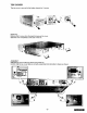
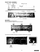
TOP COVER The top cover is secured to the bottom chassis by 3 screws REMOVAL: Remove the 3 screws from the back that secure the cover. Slide the cover completely to the back of the set. ASSEMBLY: Slide the top cover all the way to the front of the set. Confirm that the top cover tabs are correctly assembled into the bottom chassis as shown.
FRONT PANEL The front panel is secured to the bottom chassis by the side tabs. TAB PULL FLAT CABLE UPWARDS FLAT CABLE TAB REMOVAL Unplug the flat cable from the A-Board as shown above. Grab the cable from the center and pull carefully, do not pull the cable from the sides. Push the left and right sides of the bottom chassis near the tabs, to release the front panel.
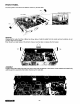
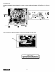
FRONT PANEL ASSEMBLY SIGNAL LED KEY BUTTONS VIDEO OUT LEDS / / Panas_c [] 'irrT lil' llil F _: / POWER BUTTON K-BOARD GND METAL SCREW FLAT CABLE DISASSEMBLY Remove the screw and the GND metal. Open the locking tabs to release the K-Board from the panel. The IR guide and the SIGNAL LED panel are mounted into a plastic guide on the panel.
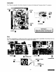
A-BOARD A-Board is secured to bottom chassis by 4 screws, 5 screws on the back, washer and the Hex nut on the tuner jack. SCREW SCREW SCREW SCREW, The connector has a tab, try to pull the connector from this tab with a flat screw. TAB Keep and re-use all hardware from (Screws, nuts, washer). I original set.
P-BOARD The P-Board is secured to the bottom chassis by 4 screws on the base and 2 screws on the A.C. connector. Ill SCREW SCREW 2 SCREWS Keep and re-use all hardware from nuts, washers).
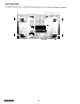
BOTTOM VIEW The bottom chassis include 4 rubber-feet, they are )laced in the four corners on the base of the chassis.
PACKING BOX Assembly the box as shown: BACK BACK FRONT FRONT BACK FRONT FRONT -9-
CUSHION BOX Assembly the cushion box as shown.
PACKING Insert Place Keep Place the the the the cushion box into the packing box as shown. reinforcement carton on the rear side of the assembly. notch of the cushion box to the front. remote control on the left side and the AC cord on the right side. REINFORCEMENT CARTON PACKING THE SET Place the set inside the plastic bag (450x400mm) and fold the remaining bag on top of the set and fix it with tape as shown. The fanbag (manuals, warranty, service center sheet, etc.
REPLACEMENT PARTS LIST FOR REBURBISHED ReF,No.
-13- I tIII]-'l I_
\ -14-
-15-
COMPLETE REPLACEMENT Model: PARTS LIST TU-DST52F Important Safety Notice: Components printed in BOLD TYPE have special characteristics any of these components use only manufacturer's specified parts. REF NO_ DESCRIPTION [_.,' REF NO. important for safety.
COMPLETE REPLACEMENT PARTS LIST Model: TU-DST52F Important Safety Notice: Components printed in BOLD TYPE have special characteristics any of these components use only manufacturer's specified parts. FIEF NO_ REF NO. PART NO. important for safety. DESCRIP_ON C8507 ECJ2VF1 C104Z CAP, C .1UF-Z-16V C8561 ECJ1vF1C104Z CAP,C .10UF-Z-16V C8508 ECJIVFIC104Z CAP, C .10UF-Z-16V C8562 ECJIVFlClO4Z CAP,C .10UF-Z-16V C8509 ECJ1VFIC104Z CAP, C .
COMPLETE REPLACEMENT Model: PARTS LIST TU-DST52F Important Safety Notice: Components printed in BOLD TYPE have special characteristics important for safety. When replacing any of these components use only manufacturer's specified parts. REF NO. PART NO. DESCRIPTION C8628 ECJ2VFlCl04Z CAP,C .1UF-Z-16V C8681 ECA1CM101B CAP, E 100UF/16V C8629 ECJ2VF1C104Z CAP,C .1UF-Z-16V C8682 ECAlCM 101B CAP, E lOOUF/16V C8630 ECJ2VFICIO4Z CAP,C .1UF-Z-16V C8683 ECJ2VF1C104Z CAP,C .
COMPLETE REPLACEMENT Model: PARTS LIST TU-DST52F Important Safety Notice: Components printed in BOLD TYPE have special characteristics any of these components use only manufacturer's specified parts. REF No.; PARTNO.' _ESCRiPTION REF NO. important for safety. When replacing PART NO; C8772 ECJ2VFlCl04Z CAP,C .1UF-Z-16V C8977 ECJ2VF1CIO4Z CAP,C .1UF-Z-16V C8773 ECJ1VF1C104Z CAP,C .10UF-Z-16V C8979 ECJIVClH050C CAP,C 5PF-C-50V C8774 ECJIVF1C104Z CAP, C .
COMPLETE REPLACEMENT PARTS LIST Model: TU-DST52F Important Safety Notice: Components printed in BOLD TYPE have special any of these components use only manufacturer's specified parts. E.C.P,,O" characteristics important for safety.
COMPLETE REPLACEMENT PARTS LIST Model: TU-DST52F Important Safety Notice: Components printed any of these components use only manufacturer's in BOLD TYPE have special specified pads. REF NO. characteristics important PART NO. for safety.
COMPLETE REPLACEMENT PARTS LIST Model: TU-DST52F Important Safety Notice: Components printed any of these components use only manufacturer's PART NO. in BOLD TYPE have special specified parts, DESCRIPTION characteristics REF NO. important for safety. ERDS2TJ103T RES,C 10K-J-1/4W R8457 ERJ6GEYJ512V RES,M 5.1 K-J-I/lOW R8007 ERDS2TJ103T RES,C 10K-J-1/4W R8459 ERJ3GEYJ512V RES,M 5.1 K-J-1/32W R8008 ERDS2TJ122T RES,C 1.
COMPLETE REPLACEMENT PARTS LIST Model: TU-DST52F Important Safety Notice: Components printed in BOLD TYPE have special characteristics important for safety. When replacing any of these components use only manufacturer's specified parts.
COMPLETE REPLACEMENT PARTS LIST Model: TU-DST52F Important Safety Notice: Components printed any of these components use only manufacturer's in BOLD TYPE have special specified parts. REF NO. characteristics important for safety. PART NO. When DESCRIPTION R8706 ERJ6ENF75ROV RES,M 75.0-F-1/10W R8800 ERJ6ENF37R4V RES,M 37.4-F-1/10W R8707 ERJ6ENF75ROV RES,M 75.0-F-1/10W R8801 ERJ6ENF37R4V RES,M 37.4-F-1/10W R8708 ERJ6ENF75R0V RES,M 75.0-F-1/10W R8802 ERJ6ENF37R4V RES,M 37.
COMPLETE REPLACEMENT Model: PARTS LIST TU-DST52F Important Safety Notice: Components printed in BOLD TYPE have special characteristics any of these components use only manufacturer's specified parts. REF NO. X9001 PART NO, J0C4405A0002 REF NO, DESCRIPTION PART important for safety. NO.
Panasonic PRINTED IN USA K02110050PL1128