ENGLISH AV Disc Recorder FRANÇAIS WJ-DR200 Before attempting to connect or operate this product, please read these instructions carefully.
ENGLISH VERSION CONTENTS PREFACE ................................................................... 1 FEATURES ................................................................. 1 PRECAUTIONS .......................................................... 2 MAJOR OPERATING CONTROLS AND THEIR FUNCTIONS ................................................... 3 ■ Front View ............................................................ 3 ■ Rear View ............................................................
PREFACE ENGLISH The WJ-DR200 AV Disc Recorder can record up to 28,000 freeze pictures with a resolution of 720 x 480 (Fine Mode) on a large capacity optical disc (DVDRAM). It can be set up to respond automatically to a sensor or alarm signal by recording the associated pictures. FEATURES • Records clear freeze pictures Applies 3D Scan Conversion to record blur-compensated, clear freeze pictures from moving images. Vertical resolution is nearly double that of conventional VCR pictures.
PRECAUTIONS • Do not expose the appliance to water or moisture, nor try to operate it in wet areas. Do take immediate action if the appliance becomes wet. Turn the power off and refer servicing to qualified service personnel. Moisture may damage the appliance and also cause electric shock. • Refer all work related to the installation of this product to qualified service personnel or system installers. • Do not block the ventilation opening or slots on the cover.
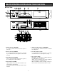
MAJOR OPERATING CONTROLS AND THEIR FUNCTIONS ■ Front View REMOTE ALARM DISC CONTROL PUSH OPEN PUSH OPEN RESET OPERATE RAM ALARM REC REC DISC AV Disc Recorder WJ-DR DISC REMOTE CONTROL ARARM REC STANDBY ALARM PAUSE REC LOCK OFF PLAY MODE 1↔ ALL SET INDDEX PLAY ON STOP RESET FIND OPERATE ALARM REC KEEP COVER CLOSED TO PREVENT INSIDE FROM DUST REC SET UP/ESC PLAY BACK SELECT T/L MODE OPEN/ CLOSE – FORMAT + BUSY PUSH OPEN DISC AV Disc Recorder ALARM REC STANDBY PAUSE WJ-DR
8. Disc cover Prevents dust from entering into the disc drive. Press to open. Do not open except to load or unload a disc. 13. Eject hole For sliding out the disc tray manually (by inserting a wire) if it is not ejected automatically when pressing the OPEN/CLOSE button (35). 9. Ventilation holes Allow air to enter the device to prevent it from overheating. Make sure not to block these holes. 21. Find button (FIND) Press to directly specify and play back a frame*2. 22.
Pressing it in paused playback will increment the playback channel (or camera ID). To play back the selected channel, press the PLAY BACK SELECT button (38). 31. Recording button (REC) Pressing the REC button will start recording in the previously defined mode. 32. Playback button (B B) Pressing the (B B) button will start playback. Holding the button down will speed up playback, releasing it will restore the normal speed. 37.
48. Audio Output/Input connectors (AUDIO OUT/IN) Provided for recording and playback of audio signals. 49. Parallel Control port (PARALLEL CONTROL) For connecting an outboard device used to remote control the Disc Recorder. 50. Serial Control port (SERIAL CONTROL) For connecting a Personal Computer and the like to remote control the Disc Recorder. 51. Camera Switching Output connector (CAMERA SW OUT) Outputs a pulse after each recorded frame. 52.
INSTALLATION AND SYSTEM CONNECTIONS INSTALLATIONS The installations described below should be made by qualified service personnel or system installers. ■ Mounting in the Rack 3. Install the Disc Recorder with the rack mounting brackets in the rack by using four screws (not included). 1. Remove the four rubber feet by removing the four screws from the bottom of the Disc Recorder. OPE RATE OPERATE Remove four rubber feet. 2.
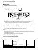
SYSTEM CONNECTIONS ■ Basic System Shown below is a typical connection scenario. Video Monitor Camera (VIDEO IN) (VIDEO OUT) WJ-DR200 VIDEO OUT 6ZA00001 AGAINST FIRE HAZARD REPLACE ONLY WITH SAME TYPE FUSE ATTENTION LED MONITOR A POWER 120V AC 60 Hz 38W VIDEO OUT 1V [ p-p ] 75Ω Manufactured by Matushita Communication Industrial Co.
WJ-DR200 VIDEO IN 6ZA00001 A POWER 120V AC 60 Hz 38W VIDEO OUT 1V [ p-p ] 75Ω Manufactured by Matushita Communication Industrial Co.
■ Terminal Board DISC: Sends a signal when DVD-RAM disc space is running low. The signal’s output parameters can be changed from the Setup menu. BUZZER OUT: Outputs a buzzer signal interlocked with the Disc Recorder’s buzzer. SYSTEM ERROR OUT: Outputs an error signal when a fatal system error occurs in the Disc Recorder. THERMAL ERROR OUT: Outputs a signal when a temperature rise is detected in the Disc Recorder.
■ External Remote Control ● Parallel Control Port Connect an external remote control switch to the PARALLEL CONTROL port on the rear of the Disc Recorder as shown below. This enables remote control of the Disc Recorder in the same way as with the control buttons on the recorder’s front panel. 13 11 12 25 24 10 23 9 22 8 21 7 20 Pin No.
● Serial Control Port Connect a personal computer to the SERIAL CONTROL port on the rear of the Disc Recorder. This port conforms both with the RS-232C and RS-485 standard and permits remote control of the Disc Recorder or storing of video data to a personal computer. Pin No.
■ Series Recording Connection The WJ-DR200 can be set up for automatic serial recording by connecting a second recorder to its Terminal Board. ● Series Recording 1 (Alternate Alarm Recording) Connect the terminals on the Terminal Boards of the MASTER and SLAVE recorder as shown below. Connect the required video and audio input to both recorders. This will enable recording alarms alternately on the MASTER and on the SLAVE recorder.
SETUP PROCEDURES • The following buttons are valid in the setup menu: The Setup Menu provides a way for controlling functions not available through direct input. Moves the cursor upward. Moves the cursor downward. Moves the cursor to the left, or selects the mode or parameter. RIGHT : Moves the cursor to the right, or selects the mode or parameter. SET: Executes the selections and displays a submenu for an item with the (*) mark.
■ MAIN Menu As shown below, the MAIN menu has seven main submenus: Set Up, System, Recording Mode 1, Recording Mode 2, Alarm Recording, Search/Play, and System Information. Six of these sub menus (System, Record Mode 1, Record Mode 2, Alarm Record, Search/Play and System Information) are further divided into additional submenus.
■ SET UP Menu SYSTEM This menu lets you change the setup or register an up to 8-character password that will allow you access to the setup menu. CLOCK START UP STATUS SERIAL SET UP VIDEO INPUT STATUS DISPLAY ALARM DISPLAY DISPLAY POSITION SERIES REC SERIES REC OUT DISC LED FUNCTION BUZZER MAIN SET UP SYSTEM REC MODE ENABLE * MODE1 * MODE2 * ALARM RECORD * SEARCH/PLAY * SYSTEM INFO * * AUG 1.98 MANUAL * * ON ON * MASTER CLOSE ↓ FULL ON 0:00 To select an item or parameter in the SYSTEM menu: 1.
5. Select one of the interface modes shown below by pressing the or button. RS-232C, RS-232C (VCR mode) or RS-485 2. Select the desired mode by pressing the or button. MANUAL: Selects manual recording mode. ALARM REC: Selects Alarm Recording mode. DISC AND ALARM REC: Selects Alarm Recording mode if a formatted disc is loaded. The default setting is RS-232C. 6. Move the cursor to the BAUD RATE parameter by pressing the or button. The default setting is MANUAL. 7.
A (CAMERA ID ON): Records only input A with multiplexed Camera ID signals. Use this parameter when the Disc Recorder is connected to a Video Multiplexer. You can select camera images in playback mode. The video pixel number (resolution) is fixed at 720 * 240. A (CAMERA ID OFF): Records only input A without multiplexed Camera ID signals. A+B (CAMERA ID OFF): Records input A and B without multiplexed Camera ID signals. Use this parameter when two cameras are connected to the Disc Recorder.
● Series Recording Setup 1. Move the cursor to the DISC LED FUNCTION parameter in the SYSTEM menu by pressing the or button. This item lets you designate the master and the slave recorder when more than one Disc Recorder is used for series recording. 2. Select either SPACE or FULL by pressing the or button. SPACE: Signal is output when disc space is running low (interlocks the signal with the DISC indicator on the Disc Recorder’s front panel). See page 3. FULL: Signal is output when the disc is full. 1.
The REC MODE 1 or REC MODE 2 menu shown below appears on the monitor screen. 2. Select the desired mode by pressing the button. FINE: For enhanced sharpness NORMAL: For normal picture quality ROUGH: For lower picture quality REC MODE1 VIDEO PIXEL VIDEO QUALITY AUDIO RECORD CAPTURE MODE ENDLESS 720 *480/3DIM ON FINE OFF SINGLE SHOT OFF or The default setting is FINE. ● Audio Recording Setup This item lets you enable or disable audio recording.
● Capture Rate If you set the CAPTURE MODE parameter to MULTI SHOT or TIME LAPSE, make the necessary settings in the respective submenus shown on the following pages. Refer to the Multi Shot menu on page 21 or Time Lapse menu on page 22 for details. This item lets you specify the interval (seconds) for recording of multiple freeze pictures. 1. Move the cursor to the CAPTURE RATE parameter in the MULTI SHOT menu by pressing the or button. ● Endless Recording Setup 2.
● Pre/Post Frames 2. Select either pattern by pressing the or button. SAME AS ALARM: Same recording pattern as for alarm activation DIFF FROM ALARM: Different recording pattern than for alarm activation This item lets you specify the number of pre-frames. A pre-frame is a frame recorded during standby for manual recording or prior to input of the alarm signal in alarm recording.
● Recording Pattern 2. Select TIME LAPSE * by pressing the or button, then press the SET button. The TIME LAPSE menu shown below appears on the monitor screen. When the CAMERA INPUT parameter in the VIDEO INPUT menu is set to A+B (CAMERA ID OFF), this item lets you select recording of pre and postframes from input A and/or B. TIME LAPSE(MODE* ) CAPTURE RATE (RECORD TIME PRE FRAMES REC PATTERN SENSOR REC PRE FRAMES POST REC PATTERN MANUAL REC ALARM RECORD PARTITION AUTO START 1.
● Auto Start Setup • Post Recording Pattern This item is available only if the CAMERA INPUT parameter in the VIDEO INPUT menu is set to A+B (CAMERA ID OFF). It lets you select recording of pre and post-frames from input A and/or B when there is sensor input from the SENSOR IN terminal. This item lets you enable or disable automatic Time Lapse Recording, when the Disc Recorder’s power is turned on. 1. Move the cursor to the AUTO START parameter in the TIME LAPSE menu by pressing the or button. 1.
● Video Pixels (Resolution) Setup ● Capture Rate This item lets you select the pixel number (number of horizontal x vertical picture elements) or resolution of the video picture. This item lets you specify the interval (seconds) for recording of multiple freeze pictures. 1. Move the cursor to the CAPTURE RATE parameter in the MANUAL REC ALARM menu by pressing the or button. 1. Move the cursor to the VIDEO PIXEL parameter in the MANUAL REC ALARM menu by pressing the or button. 2.
To select an item from the ALARM RECORD menu: 4. Select ON by pressing the or button then press the SET button. ON: Time Lapse Program Timer Recording for the specified day and time is enabled. Select this parameter to set START and END. OFF: Time Lapse Program Timer Recording is disabled. 1. Move the cursor to the desired item by pressing the or button. 2. Select a parameter by pressing the or button. 3. Press the SET UP/ESC button to return to the previous MAIN menu, if desired. 5.
1. Move the cursor to the TIMER DURATION parameter in the ALARM RECORD menu by pressing the or button. 1. Move the cursor to the PROGRAM TIMER parameter in the ALARM RECORD menu by pressing the or button. 2. Select an alarm duration between 1 second and 5 minutes as shown below by pressing the or button. 2. Select either ON or OFF by pressing the button. or Enables Program Timer recording. To program the timer, you need to make the necessary settings in the associated submenu.
4. To edit the selected program, press the SET button to move the cursor to the selected program editing area. To selects parameter from the SEARCH/PLAY menu: 1. Move the cursor to the desired parameter by pressing the or button. 5. Move the cursor to the position to be edited by pressing the , , or button. 2. Select the mode by pressing the 6. Select the desired time by pressing the (+) or (–) button. 3. Press the SET UP/ESC button to return to the previous MAIN menu, if desired. 7.
2. Select either RECORD TIME or RECORD NUMBER by pressing the or button. LOOP: Repeats playing back the selected number of playback records. SINGLE CYCLE: Goes on standby after playing back the selected number of records. RECORD TIME: Searches the disc by recording time. RECORD NUMBER: Searches the disc by record number. The default setting is LOOP. ● Playback Rate Setup The default setting is RECORD TIME. This item lets you select the playback rate in seconds. ● Thumbnail Display Setup 1.
■ System Information Menu All items other than those described above provide information on the Disc Recorder’s system status and cannot be changed from this menu. This menu allows you to specify the sleep operation mode of the DVD drive and lists status information for the Disc Recorder. ■ Label Setup MAIN The Disc Recorder can display the point of origin of any incoming alarm or sensor signal on the monitor screen. This is done by assigning three types of labels consisting of up to 8 characters.
3. Move the cursor on the desired character in the table by pressing the , , or button. A B C L M N W X Y a b c l m n w x y 1 2 3 ( ) . ? = + CLEAR 4. Press the SET button to pick up the character, and place it in the editing area. 5. Repeat the above procedures 3 and 4 until the label is completed. D O Z d o z 4 , - E F G H I J K P Q R S T U V e f g h i j k p q r s t u v 5 6 7 8 9 0 _ ’ ” : ; & # ! * / % $ 6.
2 Move the cursor to the FORMAT parameter in the LOGICAL FORMAT menu by pressing the or button. SET_UP PASSWORD A B C D E F G H I J K L M N O P Q R S T U V W X Y Z 1 2 3 4 5 6 7 8 9 0 3. Select PASSWORD by pressing the butor ton, then press the SET button. The FORMAT PASSWORD table shown below appears on the monitor screen. CLEAR (☞SET) FORMAT PASSWORD A B C D E F G H I J K L M N O P Q R S T U V W X Y Z 1 2 3 4 5 6 7 8 9 0 3.
6. Move the cursor to ENTER in the table, then press the SET button. “OK” or “NG” is displayed in the lower center of the monitor screen. OK: Correct password, access to setup menu permitted. NG: Wrong password, access to setup menu denied. Enter correct password. DISC PASSWORD A B C D E F G H I J K L M N O P Q R S T U V W X Y Z 1 2 3 4 5 6 7 8 9 0 CLEAR (☞SET) 7. If the password is correct, the display will return to the previous MAIN menu. ● Changing/Deleting a Password 3.
OPERATING PROCEDURES FORMATTING THE DISC The DVD-RAM Disc requires formatting before it can be used for storing data. Follow the procedures described below to format the DVD-RAM Disc on the Disc Recorder. OPEN/ CLOSE SET UP/ESC Disc Tray 1. Turn on the Power Switch located on the rear of the Disc Recorder. OPERATE PUSH OPEN 2. Press the Disc Cover and Control Panel to open the covers located on the front of the Disc Recorder. 3.
● Physical Format Menu STATUS DISPLAY This menu lets you perform physical formatting of the DVD-RAM Disc after logical formatting. The process involves checking of all disc sectors for logical and physical errors and then substituting the damaged areas. Normally use the Logical Format for formatting the disc. The Status Display window shows the system status of the Disc Recorder. It is displayed on the monitor screen during recording and playback and contains the following information. 1.
● Manual Record with Standby RECORDING 1. Press the REC button while holding down the PAUSE button. yREC is displayed in the lower center of the monitor screen, and the recorder stands by for recording in the selected mode. ■ Recording Modes The WJ-DR200 Disc Recorder has three recording modes to match your specific needs. Refer to the Recording Mode Menu on page 19 for making the necessary settings. Single Shot Recording: Records one freeze picture in response to a command or signal input.
3. The recorder repeats procedure 2 until the ALARM REC STANDBY button is pressed. SYSTEM 4. To stop alarm recording, press the ALARM REC STANDBY button. CLOCK START UP STATUS SERIAL SET UP VIDEO INPUT STATUS DISPLAY ALARM DISPLAY DISPLAY POSITION SERIES REC SERIES REC OUT DISC LED FUNCTION BUZZER ■ Series Recording Series Recording refers to recording on two series-connected Disc Recorders. Refer to Series Recording in the SYSTEM menu on page 19 for the necessary settings.
■ Other Recording Functions Besides three recording modes, the Disc Recorder offers a number of recording functions accessed from the setup menu. TIME LAPSE(MODE1) CAPTURE RATE (RECORD TIME PRE FRAMES REC PATTERN SENSOR REC PRE FRAMES POST REC PATTERN MANUAL REC ALARM RECORD PARTITION AUTO START 0.20 sec 1h35m) 0 SAME AS ALARM OFF 50 ON ● Auto Start Time Lapse Recording This function starts recording automatically in Time Lapse Recording mode when the recorder is powered up.
PLAYBACK T/L MODE ■ Basic Playback – FORMAT + The recorder has the following two basic playback functions. 012345aMA PLAY AUG 1.98 14:15:05 P :CAPTURE RATE (A) Playback/Reverse Playback Plays back the record recorded last in forward or reverse mode. Auto Forward/Auto Reverse Playback Plays back all recorded records continuously in forward or reverse mode. 2. Press the PLAY BACK SELECT button.
● Forward/Reverse Single Frame Playback 2. Press the (or ) button to select the next page (or previous page), if applicable. Press the (or ) button in paused playback. (or ) is displayed in the lower center of the monitor screen, and playback moves one frame forward (or backward) from the paused frame. Note: Pressing the (or ) button for about 2 seconds in step 2 will skip forward (or backward) by the number of records specified for the SKIP#RECORD parameter in the SEARCH/PLAY menu.
Note: Pressing the (or ) button for about 2 seconds in step 2 will skip forward (or backward) by the number of records specified for the SKIP#RECORD parameter in the SEARCH/PLAY menu. 6. Press the SET button to play back the blinking record. 4. Move the cursor to the thumbnail to be displayed by pressing the , , or button. Notes: • Pressing the FIND button in the Thumbnail window will display the thumbnail pictures, each with a search editing area at the bottom.
3. Select the password in the menu, then press the SET button to display the Deny Access setup menu as shown below. NO 012348aMS 012347 MA 012346 M 012345 SS 012344aSA 012343aSA 012342 SS 012341 S RECORD TIME AUG 1.98 14:59:55 AUG 1.98 14:58:25 AUG 1.98 14:54:15 AUG 1.98 13:10:10 AUG 1.98 12:55:30 AUG 1.98 12:55:00 AUG 1.98 12:35:30 AUG 1.98 12:25:30 HIDE RECORD NO 4. Press the (or previous) page. 01238 ) button to scroll to the next (or 5.
APPENDIX ● Time Lapse Recording Time Note: Time Lapse recording time varies slightly depending on the images recorded. 1. Without Audio (for a 20-partition disc) (50390 x Rate x 20) Image Data Size Recording time = (P + 0.0396) x 3600 Pixel Number FINE Rate: Recording rate (seconds/frame) 720 ∗ 480 34 P: Image data size (see table) 720 ∗ 240 18 NORMAL ROUGH 22 14 11 8 2. With Audio (for a 20-partition disc) (50390 x Rate x 20) Recording time = (P +A + 0.
Recording Time in Time Lapse Recording (hours : minutes) Pixel Number 720 ∗ 480 Audio ON Audio OFF CAPTURE RATE 0.03 FINE 0.07 0:30 0:48 1:13 0:32 0:50 1:18 0.10 0:48 1:12 1:50 0:49 1:16 1:58 0.17 1:18 2:01 3:05 1:21 2:06 3:18 0.20 1:34 2:25 3:42 1:38 2:32 3:58 0.33 2:34 3:52 5:48 2:44 4:13 6:38 NORMAL ROUGH FINE NORMAL ROUGH 0.
■ Checking Your Password 4. Pressing the following buttons will display your password within brackets for a short period of 5 seconds. To check your SETUP Password: Press the and STOP buttons simultaneously with the LOCK switch in ON position. To check your FORMAT Password: Press the FORMAT buttons (+ and –) simultaneously with the LOCK switch in ON position. To check your DISC Password: Press the ALARM REC STANDBY and REC buttons simultaneously.
■ Cleaning the DVD Drive 5. Press the OPEN/CLOSE button on the Control Panel to slide in the tray. Cleaning will start automatically. The DVD drive needs to be cleaned after prolonged use. Use the optional cleaning disc as shown below for cleaning the drive. Panasonic PD Lens Cleaner (Wet-type) LF-K123LCA 6. After 30 seconds, the message “DRIVE ERROR” appears on the monitor screen and the BUSY indicator begins to blink in green. 7.
SPECIFICATIONS General Power Source: Power Consumption: Ambient Operating Temperature: Ambient Operating Humidity: Dimensions: Weight: 120 V AC, 60 Hz 38 W +5°C - +40°C (41°F - 104°F) Less than 90 % 420 (W) x 88 (H) x 350 (D) mm 16-9/16” (W) x 3-7/16” (H) x 13-3/4” (D) 7 kg (15.4 lbs.) Input and Output Video Input A: 1.0 V[p-p]/75 Ω NTSC Composite Video Signal with 75 Ω Automatic Termination/Looping through (x1) Y Signal; 0.714 V[p-p], C Signal; 0.286 V[p-p]/75 Ω S-Video Signal (x1) Video Input B: 1.
STANDARD ACCESSORY AC Power Cord ..............................................................1 pc.
Security and Digital Imaging Systems Company A Division of Matsushita Electric Corporation of America Executive Office: One Panasonic Way 3E-7, Secaucus, New Jersey 07094 Regional Offices: Northeast: One Panasonic Way, Secaucus, NJ 07094 (201) 348-7303 Southern: 1225 Northbrook Parkway, Suite 1-160, Suwanee, GA 30024 (770) 338-6838 Midwest: 1707 North Randall Road, Elgin, IL 60123 (847) 468-5211 Western: 6550 Katella Ave., Cypress, CA 90630 (714) 373-7840 PANASONIC CANADA INC.