
User Guide


23
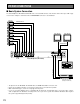
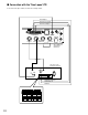
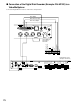
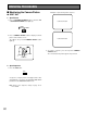
■ Basic System Connection
The Video Multiplexers WJ-FS409 and WJ-FS416 are connected with cameras, video monitors and a Time Lapse VTR. A typi-
cal connection example is shown below. The ALARM/REMOTE connector is described later.
• The figure shows the WJ-FS409. The WJ-FS416 has 16 VIDEO IN and OUT connectors each.
• Refer to the operating instructions of each system component for connection and operation.
• With certain monitor types, colour noise may appear in the picture.
• In case of connecting multiple devices compatible with the Panasonic Security Data mode, connect the unit in a daisy-
chain configuration. The allowable connecting devices are up to 16 in a system. The maximum allowable cable length of
the system is approximately 500 m (1 650 ft).
SYSTEM CONNECTIONS
Cameras
Video Monitor
Video Monitor
System Controller
VIDEO INPUT
VIDEO OUTPUT
Video Multiplexer (WJ-FS409)
VIDEO INPUT
VIDEO OUTPUT
CAMERA SWITCH
Time Lapse VTR or
Digital Disk Recorder
(Example: WJ-HD100)
SIGNAL
GND
ALARM/REMOTE
OUT
IN
VIDEO
98 7654 321
98 7654 321
PLAY IN
REC OUT
SPOT OUT
DATA
CAMERA
SW IN
MULTI
SCREEN OUT