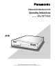
Network Interface Unit Operating Instructions Model No. OPERATE WJ-NT304 LINK RC V SND Network Interfac e Unit W J-NT30 4 Before attempting to connect or operate this product, please read these instructions carefully and save this manual for future use.
We declare under our sole responsibility that the product to which this declaration relates is in conformity with the standards or other normative documents following the provisions of Directives EEC/73/23 and EEC/89/336. Wij verklaren als enige aansprakelijke, dat het product waarop deze verklaring betrekking heeft, voldoet aan de volgende normen of andere normatieve documenten, overeenkomstig de bepalingen van Richtlijnen 73/23/EEC en 89/336/EEC.
The serial number of this product may be found on the surface of the unit. You should note the serial number of this unit in the space provided and retain this book as a permanent record of your purchase to aid identification in the event of theft. Model No. Serial No. For Canada This Class A digital apparatus complies with Canadian ICES-003. For U.S.A NOTE: This equipment has been tested and found to comply with the limits for a Class A digital device, pursuant to Part 15 of the FCC Rules.
Important Safety Instructions 1) Read these instructions. 2) Keep these instructions. 3) Heed all warnings. 4) Follow all instructions. 5) Do not use this apparatus near water. 6) Clean only with dry cloth. 7) Do not block any ventilation openings. Install in accordance with the manufacturer's instructions. 8) Do not install near any heat sources such as radiators, heat registers, stoves, or other apparatus (including amplifiers) that produce heat.
Limitation of Liability THIS PUBLICATION IS PROVIDED "AS IS" WITHOUT WARRANTY OF ANY KIND, EITHER EXPRESS OR IMPLIED, INCLUDING BUT NOT LIMITED TO, THE IMPLIED WARRANTIES OF MERCHANTABILITY, FITNESS FOR ANY PARTICULAR PURPOSE, OR NON-INFRINGEMENT OF THE THIRD PARTY’S RIGHT. THIS PUBLICATION COULD INCLUDE TECHNICAL INACCURACIES OR TYPOGRAPHICAL ERRORS. CHANGES ARE ADDED TO THE INFORMATION HEREIN, AT ANY TIME, FOR THE IMPROVEMENTS OF THIS PUBLICATION AND/OR THE CORRESPONDING PRODUCT (S).
Preface Network Interface Unit WJ-NT304 is designed to capture images from analog cameras and compress the images in JPEG or MPEG-4 files. By connecting to a network (LAN) or the Internet, images and audio from the camera can be monitored on a PC via a network.*1 *1 It is necessary to configure the network settings of the PC and its network environment to monitor images and audio from the camera on the PC. It is also necessary that a web browser is installed on the PC.
About These Operating Instructions There are 2 sets of operating instructions for the WJ-NT304 as follows. • Installation Guide (book, these operating instructions) • Network operating instructions (PDF) The "Installation Guide" contains descriptions of how to install and connect this unit, and how perform the required network settings. Refer to the "Network Operating Instructions (PDF)" on the provided CD-ROM for descriptions of how to perform the unit settings and how to operate this unit.
Network Security As you will use this product connected to a network, your attention is called to the following security risks. 1. Leakage or theft of information through this product 2. Use of this product for illegal operations by persons with malicious intent 3. Interference with or stoppage of this product by persons with malicious intent It is your responsibility to take precautions such as those described below to protect yourself against the above network security risks.
CONTENTS Important Safety Instructions ...................................................................................................................... 4 Limitation of Liability ................................................................................................................................... 5 Disclaimer of Warranty ............................................................................................................................... 5 Preface .................................
Precautions • Do not block the ventilation opening or slots on the cover. To prevent the apparatus from overheating, place it at least 5 cm {2 inches} away from the wall. • Do not drop metallic parts through slots. This could permanently damage the apparatus. Turn the power off immediately and contact qualified service personnel for service. • Do not attempt to disassemble the apparatus. To prevent electric shock, do not remove screws or covers. There are no user-serviceable parts inside.
MPEG-4 Visual patent portfolio license This product is licensed under the MPEG-4 Visual patent portfolio license for the personal and non-commercial use of a consumer for (i) encoding video in compliance with the MPEG-4 Visual Standard ("MPEG-4 Video") and/or (ii) decoding MPEG-4 Video that was encoded by a consumer engaged in a personal and non-commercial activity and/or was obtained from a video provider licensed by MPEG LA to provide MPEG-4 Video.
Major Operating Controls and Their Functions ■ Front view w OPERATE LINK RCV SND Front cover Network Interface Unit WJ-NT304 q u WJ-NT304 e y r q Operation Indicator (OPERATE) This LED will light when the power is on. Important: • The LED will blink for around 2 minutes until the unit becomes ready to operate. • When the temperature is below 0 °C, it may take time until the unit becomes ready to operate. t SD memory card slot An SD memory card (option) is inserted into this slot. Refer to p.
■ Rear view q IN 4 3 w 2 1 u i SIGNAL GND IN o DC12V IN G OUT 4 3 VIDEO 2 4 3 2 1G 4 3 2 1 !0 OUT 1 OUT AUDIO r q Video input connectors 1 to 4 (VIDEO IN 1 to 4) (BNC, 75 Ω, with auto termination) These connectors accept video input signals from cameras or recorders. w Video output connectors 1 to 4 (VIDEO OUT 1 to 4) (BNC, loop-thru) These connectors loop thru video input signals supplied to VIDEO IN connectors 1 to 4.
Rack Mounting z Remove the rubber feet (4 pcs.) on the bottom of the unit. Remove the rubber feet. x Install the rack mounting brackets (Option: Refer to the following.) on both sides of the unit. Using the mounting screws (4 pcs.) for the rack mounting brackets, fix them firmly. 1. When installing one unit: Model No.: WV-Q204/1S • Rack mounting bracket (Large) x 1 • Rack mounting bracket (Small) x 1 • Rack mounting screws (M3 x 8: 6 pcs.) 2. When installing two units: Model No.
Connection Example ■ When connecting to a network using a PoE device (hub) LAN cable (category 5 or better, straight) PC Hub Camera Monitor Enternet cable (Category 5 or better, straight) Camera 電 源 入 切 OPERATE LINK RCV SND Network Interface Unit WJ-NT304 Dome camera 電 源 入 切 AC adapter (Provided) Dome camera AUDIO OUT 電 源 入 切 AUDIO IN 電 源 入 切 Power cord (Provided) Speaker (Option) Audio amplifier To an outlet Microphone (Option) Audio amplifier ■ When connecting with a P
Insert/Remove an SD Memory Card ■ How to insert an SD memory card Important: • Before inserting a SD memory card, make sure that the power of the unit is turned off. z Open the front cover. c Insert an SD memory card into the SD memory card slot. OPERAT E LINK RCV SN D OPERAT E LINK Networ k Interia ce Unit RCV SND WJ-NT3 04 Front cover SD memory card slot x Detach the SD memory card slot cover by loosening the screw. v Attach the cover and tighten the screw. b Close the front cover.
Configure the Network Settings ■ Install the software Before installing the software, read the readme file on the provided CD-ROM first. ● Software included on the provided CD-ROM • Panasonic IP Setup Software Configure the network settings of the unit. Refer to the following for further information. • Viewer Software "Network Camera View3" It is necessary to install the viewer software "Network Camera View3" to display images on a PC. Install the viewer software by double-clicking the "nwcv3 setup.
Troubleshooting Before asking for repairs, check the symptoms with the following table. Contact your dealer if a problem cannot be solved even after checking and trying the solution or if the problem is not described below. Symptom Power is not turned on. Setup menu of matrix switcher system cannot be displayed. Cause/solution Reference pages Check if the power plug is properly connected to the AC outlet. – Check if the DC plug of AC adapter is properly inserted into the DC IN jack of this monitor.
Specifications ■ Network Interface Unit Power source: Power consumption: Ambient temperature: Ambient humidity: Video input connectors: Video output connectors: Audio input connector: Audio output connector: Serial port: Parallel port: Resolution: Image compression method: Audio compression method: Protocol: Camera control: Network: Security: OS: Browser: Dimensions: Weight: 12 V DC, 1.0 A (using the supplied AC adapter) Approx.
Information on Disposal for Users of Waste Electrical & Electronic Equipment (private households) This symbol on the products and/or accompanying documents means that used electrical and electronic products should not be mixed with general household waste. For proper treatment, recovery and recycling, please take these products to designated collection points, where they will be accepted on a free of charge basis.