Network Interface Unit Network Operating Instructions Model No. OPERATE WJ-NT314 LINK RC V SND Network Interfac e Unit W J-NT31 4 Before attempting to connect or operate this product, please read these instructions carefully and save this manual for future use.
CONTENTS Preface ..................................................................................................................................... 3 About these operating instructions ....................................................................................... 3 Trademarks and registered trademarks ............................................................................... 3 Viewer Software ...................................................................................................
Preface About these operating instructions There are 2 sets of operating instructions for the WJ-NT314 as follows. • Operating Instructions (Book) • Network operating instructions (PDF) These operating instructions contain descriptions of how to operate this product using a PC via a network and of how to configure the settings. Refer to the operating instructions for descriptions of how to install this product and of how to connect to a network.
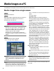
Monitor Images on a PC The following are descriptions of how to monitor images from the unit on a PC. Monitor images from a single camera Step 1 Start up the web browser. Step 2 Enter the IP address designated using the Panasonic IP setup software in the address box of the browser. (Example: http://192.168.0.10/) Important: • When the HTTP port number is changed from "80", enter "http://IP address of the unit +: (colon) + port number" in the address box of the browser, for example, "http://192.168.0.
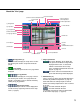
About the "Live" page !9 Full screen button !8 Alarm occurrence indication button !7 Camera title !6 Unit title @0 One shot button @1 Mic input button @2 Audio output button q [Setup] button @3 Time and date w [Live] button e [1] to [4] buttons r Multi-screen buttons t Image type buttons @4 Main area !4 Frame y AUX buttons !5 Track !2 BRIGHTNESS buttons u B/W button !3 Preset i ZOOM buttons !0 AUTO MODE !1 Control pad/buttons o FOCUS buttons q [Setup] button (*1) Click this button to display
u B/W button (*2) Click the desired button to switch color (colour) of the displayed images between color (colour) and B/W. : Images will be displayed in B/W (black and white). : Images will be displayed in color (colour). : Activates Auto 1 mode. (The camera selects black and white mode if the picture is dark, or color mode if the picture is bright enough.) If the camera has only one AUTO mode, click this button. : Activates Auto 2 mode. (The camera detects the light source type to prevent malfunction.
!4 Frame Displays/hides the frame when a person is detected. Refer to page 11 for further information. !5 Track Displays/hides the track of motion made by the detected person. Refer to page 11 for further information. !6 Unit title The unit title entered for "Unit title" on the [Basic] tab will be displayed. (☞ page 20) !7 Camera title The camera title set for [Camera title] will be displayed.
*1 Operable by only users and hosts whose access level is "1. Administrator" *2 Only operable by users and hosts whose access level is "1. Administrator" or "2. Camera control" when "ON" is selected for "User authentication" (☞ page 46) and "Host authentication" (☞ page 47). *3 Operable by users and hosts who belong to the access level selected for "Authentication" on the [Audio] tab of the "Camera setup" page. (☞ page 32) Refer to page 46 for further information about the access level.
Action at an Alarm Occurrence The alarm action will be performed when the following alarm occur. Alarm type Terminal alarm: When connecting an alarm device such as a sensor to the connector terminal (Alarm Input No. 1 to 4) on the rear of the unit, the alarm action (unit action at an alarm occurrence) will be performed when the connected alarm device is activated. Alarm action to be performed differs depending on the settings configured on the [Alarm] tab.
About the image recognition function AVMD, which is one of the image recognition functions, are featured in this unit. It is possible to detect moving, abandoned, or removed objects in the shooting area by setting the detection program in advance. (☞ page 34) When an abandoned or removed object is detected, the frame and track, are displayed on the live images. (☞ page 12) Auto track for the detected object is also possible using another analog camera.
• Weather condition is extremely poor. When setting AVMD, check the performance during both daytime and nighttime after setting the detection area, according to the installation place of camera and the assumed motion of object. If the AVMD is activated improperly or not activated even after the setting, use a sensor. Luminance level affects detection of abandoned or removed objects. It is recommended to use this unit in a room where luminance level is stable.
Transmit Images onto an FTP Server Images can be transmitted to an FTP server. By configuring the following settings, transmission of images captured at an alarm occurrence or captured at a designated interval to an FTP server will become available. Important: When using this function, set the user name and the password to access the FTP server to restrict users who can log into the FTP server.
Save images on the SD memory card when failed to transmit images by the FTP periodic transmission function Images that have failed to transmit using the FTP periodic transmission can be saved automatically on the SD memory card. When using the "SD memory REC" function of a Panasonic’s network disk recorder, select "OFF" for the "FTP periodic transmission" function. (☞ page 55) Refer to the operating instructions of network disk recorder for further information.
Step 3 Move the current directory to "sd_data" and obtain images. Note: • When logging in the unit, each directory will be displayed. Images on the SD memory card can be found in the "sd_data" directory. Move to the "sd_data" directory and obtain images. sd_data Directory ftp : : : : log Directory (year/month/day) Directory (hour/minute) 070101 0123 070102 : : : : An image failed to transmit by the FTP periodic transmission function (Ex. img_010701010123000.
About the Network Security of This Unit Equipped security functions The following security functions are featured in this unit. q Access restrictions by the host authentication and the user authentication It is possible to restrict users from accessing the unit by setting the host authentication and/or the user authentication to on. (☞ pages 46 and 47) w Access restrictions by changing the HTTP port It is possible to prevent illegal access such as port scanning, etc. by changing the HTTP port number.
Display the Setup Menu and Configure the Settings of the Unit using a PC The settings of the unit can be configured on the setup menu. The setup menu is only operable by users whose access level is "1. Administrator". How to display the setup menu Step 1 Display the "Live" page. (☞ page 4) Step 2 Click the [Setup] button on the "Live" page. → The window with the user name and password entry fields will be displayed. Step 3 Click the [OK] button after entering the user name and the password.
How to operate the setup menu Important: When there are two [SET] buttons (or [REG] buttons) or more on the page, click the respective button to the edited setting item. A A-1 Menu button Setup page Step 1 Click the desired button in the frame on the left of the window to display the respective setup menu.
About the operation window !2 Status display area q [Live] button w [Basic Setup] button e [Camera setup] button r [Multi-screen setup] button !3 Setup page t [Video analytics setup] button y [Alarm setup] button u [Authentication setup] button i [Server setup] button o [Network setup] button !0 [Maintenance] button !1 [Help] button q [Live] button The "Live" page will be displayed. w [Basic setup] button Click this button to display the "Basic setup" page.
i [Server setup] button Click this button to display the "Server setup" page. The settings relating to the mail server and the FTP server to which the unit accesses can be configured on the "Server setup" page. Refer to page 48 for further information. o [Network setup] button Click this button to display the "Network setup" page.
Configure the basic settings of the unit [Basic setup] The basic settings such as time and date and unit name, and the settings relating to the NTP server and the SD memory card can be configured on the "Basic setup" page. The "Basic setup" page has 4 tabs of the [Basic] tab, the [NTP] tab, [SD memory card] tab, and the [RS485 setup] tab. Configure the basic settings [Basic] Click the [Basic] tab on the "Basic setup" page. The settings such as the unit name, time and date, etc.
[Alarm status update mode] Select an interval to notify the unit status (alarm status, audio status, etc.) from the following. When the status of the unit changes, the alarm occurrence indication button, the mic input button, or the audio output button will be displayed to notify of the unit status. Polling (30 sec): Updates the status each 30 seconds and provide notification of the unit status. Real time: Provide notification of the unit status when the status has changed.
Configure the settings relating to the NTP server [NTP] Click the [NTP] tab on the "Basic setup" page. (☞ page 20) The settings relating to the NTP server such as the NTP server address, port number, etc. can be configured on this page. [Time zone] Select a time zone according to the location where the unit is in use. Default setting: (GMT) Greenwich Mean Time: Dublin, Edinburgh, Lisbon, London [Time adjustment] Select the time adjustment method from the following.
Configure the settings relating to SD memory card [SD memory card] Click the [SD memory card] tab on the "Basic setup" page. (☞ page 20) The settings relating to the SD memory card can be configured on this page. Note: Notification will be provided when the remaining space of the SD memory card reached the values above. For example, notification will be provided for the destination IP address when the remaining space reaches 50 % or less when "50%" is selected.
Important: • Before formatting the SD memory card, it is necessary to select "Use" for "SD memory card" on the [SD memory card] tab of the "Basic setup" page (☞ page 55) and "OFF" for "FTP periodic transmission" on the [FTP] tab of the "Network setup" page (☞ page 49). • Format the SD memory card only by clicking the [Execute] button on the setup menu. Otherwise, the following functions using the SD memory card may not work properly with this unit.
Image capture size: QVGA Size of SD memory card Image quality 0 (Super fine) 1 (Fine) 2 3 4 2 GB Approx. 24 000 pics Approx. 26 000 pics Approx. 27 000 pics Approx. 28 000 pics Approx. 30 000 pics 1 GB Approx. 12 000 pics Approx. 13 000 pics Approx. 13 500 pics Approx. 14 000 pics Approx. 15 000 pics 512 MB Approx. 6 000 pics Approx. 6 500 pics Approx. 6 750 pics Approx. 7 000 pics Approx. 7 500 pics 256 MB Approx. 3 000 pics Approx. 3 250 pics Approx. 3 375 pics Approx. 3 500 pics Approx.
Configure the settings relating to images and audio [Camera setup] The settings relating to JPEG/MPEG-4 images and camera operation can be configured on the "Camera setup" page. The "Camera setup" page has 4 tabs of the [JPEG/MPEG-4] tab, the [Camera] tab, [Audio] tab and the [Coaxial setup] tab. Configure the settings relating to JPEG/MPEG-4 image [JPEG/MPEG-4] Click the [JPEG/MPEG-4] tab on the "Camera setup" page.
■ JPEG setup [Refresh interval (JPEG)] Select an interval to refresh the displayed JPEG image from the following. NTSC model: 0.1 fps/0.2 fps/0.33 fps/0.5 fps/1 fps/ 2 fps/3 fps/5 fps */6 fps */10 fps */15 fps */30 fps * Default setting: 3 fps PAL model: 0.08 fps/0.17 fps/0.28 fps/0.42 fps/ 0.83 fps/1.7 fps/2.5 fps/4.2 fps */5 fps */8.3 fps */ 12.5 fps */25 fps * Default setting: 2.
and "Unicast port2 (Audio)" will automatically be selected when transmitting images and audio from the unit. When it is unnecessary to fix the port number for MPEG-4 image transmission such as when using in a particular LAN environment, it is recommended to select "Unicast port (AUTO)". Unicast port (MANUAL): Up to 8 users can access a single camera concurrently. It is necessary to select "Unicast port1 (Image)" and "Unicast port2 (Audio)" manually to transmit images and audio from the unit.
[Number of JPEG monitoring clients] Select the number of users of each channel to monitor JPEG images on the browser. [Number of JPEG receiving devices] Select the number of connected devices of each channel to receive JPEG images. [Refresh interval of JPEG monitoring clients] The set value for refresh interval when monitoring JPEG images on the browser is displayed.
Configure the settings relating to camera [Camera] Click the [Camera] tab on the "Camera setup" page. (☞ page 26) The following are descriptions of how to display the setup menu and configure the settings relating to camera operation using the operation panel. Refer to the provided operating instructions for further information about emergency recording. [CH No.] Select a channel to configure the setting relating to the camera operation.
Configure the settings relating to audio [Audio] Click the [Audio] tab on the "Camera setup" page. (☞ page 26) The following are descriptions for when the settings relating to audio from CH1 is configured on this page. [Audio bit rate] Select "16 kbps" or "32 kbps" for the audio bit rate used to transmit/receive audio data. Default setting: 32 kbps [Mic input interval (Unit to PC)] Select an interval for audio reception from the following.
[Audio output port (PC to Unit )] Enter the transmission port number (the port number on the unit used to receive audio data transmitted from the PC). Available value: 1024 - 50000 (Only even numbers are available.) Default setting: 34004 Note: The transmission port number entered for "Audio output port (PC to Unit)" will be used only when transmitting MPEG-4 images. When "OFF" is selected for "MPEG-4 transmission" (☞ page 27), it is not necessary to enter the transmission port number.
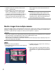
Configures the multi-screen settings [Multi-screen setup] The cameras to be used for the multi-screen display can be registered on this page. The following cameras are available for the multi-screen display. (As of August, 2007) Cameras connected to WJ-NT314, cameras connected to the network, WV-NP240 series, WV-NP1000 series, WV-NW470S series, WV-NP472, WV-NS320 series, WV-NS202, WV-NF284, WV-NS202A, WJ-NT304 [CH No.
Configure the AVMD settings [Video analytics setup] The settings relating to the detection area, depth, and schedule for AVMD can be configured on the "Video analytics setup" page. The "Video analytics setup" page has 2 tabs of the [AVMD] tab, and the [Schedule] tab. Set the detection program [AVMD] Click the [AVMD] tab on the "Video analytics setup" page. Set the detection program for AVMD. It is possible to set up to 8 preset positions (CH1 to CH4) for 8 detection programs.
Notes: • Color in the ( ) beside the icon is the color to display the detection area. • Select a parameter from "P1 (Blu)" to "P3 (Yel)" when setting an area to detect an intruder. Alarm occurs when a moving object enters the area. It may take around 2 seconds since the person is detected until the alarm occurs. • Select "P (Bro)" when setting an area to detect the object abandonment or removal. Alarm occurs when an object is taken into the area or when the object is taken away from the area.
Set the detection depth It is possible to set the depth information for each detection program both automatically and manually. • Set the depth automatically (☞ page 36) • Set the depth manually (☞ page 37) Set the depth automatically Note: To set the depth automatically, have a person move forward and backward several times within the image being detected. Step 4 The person moves forward and backward several times within the image at the preset position of the selected channel.
Set the depth manually Step 1 Click the [SET] button of "Depth correction" on the [AVMD] tab. Step 4 After drawing the marker, click the [Execute] button of "Depth calculation". → Calculation result is displayed in 3D on the screen. → The "Depth correction" menu will be displayed. Step 2 Select "Manual setup" for "Setup mode". Step 3 Draw a marker by dragging the mouse between the front side and rear side on the screen. Step 5 Click the [SAVE] button after completing the settings.
Set the AVMD schedule [Schedule] Click the [Schedule] tab on the "Video analytics setup" page.(☞ page 34) It is possible to set the schedule for each detection program. For example, to monitor the entrance and exit, it is possible to set the detection program for the entrance between 6 a.m. and 12 a.m. on Monday to Friday, and for the exit between 4 p.m. and 12 p.m. on Monday to Friday.
How to delete the set schedule Step 1 Select the schedule number from "Schedule 1" to "Schedule 8". Step 2 Uncheck the check box of the set day of the week. Step 3 Click the [SET] button after completing the settings. Step 4 To check the schedule on the time bar, click [i] and select the channel number (detection program) from the [CH No.] pull-down menu.
Configure the alarm settings [Alarm setup] The settings relating to alarm occurrences such as settings for the alarm action at an alarm occurrence and the alarm occurrence notification can be configured on the "Alarm setup" page. The "Alarm setup" page has 2 tabs of the [Alarm] tab, and the [Notification] tab. Configure the settings relating to the alarm action [Alarm] Click the [Alarm] tab on the "Alarm setup" page. The settings relating to the alarm action can be configured on this page.
Auto mode It is possible to activate auto mode for the camera connected to the video input connector of event CH (CH1 to 4) when the AVMD is detected. (When a preset position number is selected, operation starts after the camera moves to the preset position.) Auto track: Performs auto track when the camera supports auto track (AUTO TRACK). –: OFF Default setting: – The command alarm is the function that receives Panasonic alarm protocol from other Panasonic’s network devices.
Configure the settings relating to the alarm image [Alarm image setup] Click the [Alarm] tab on the "Alarm setup" page. (☞ page 40) The settings relating to the alarm image to be transmitted to the FTP server can be configured on this page. The alarm image will be transmitted to the FTP server. To transmit alarm images to the FTP server, it is necessary to configure the settings in advance.
Configure the settings relating to the alarm out connector [Alarm output setup] Click the [Alarm] tab on the "Alarm setup" page. (☞ page 40) The settings relating to the alarm output terminals (Alarm Output No. 1 to 4) can be configured on this page. Alarm Output No. 1 to 4 is associated with each alarm input of CH1 to 4. Refer to pages 40 and 42 for further information about the settings relating to the alarm action and the alarm image.
Configure the settings relating to the mail notification [Notification] Click the [Notification] tab on the "Alarm setup" page. (☞ page 40) The settings relating to the alarm mail can be configured on this page. To notify of an alarm occurrence by e-mail, it is necessary to configure the settings of the mail server. (☞ page 48) [Mail body] Enter the mail body.
Configure the settings relating to Panasonic alarm protocol [Panasonic alarm protocol] Click the [Notification] tab on the "Alarm setup" page. (☞ page 40) The settings relating to Panasonic alarm protocol can be configured on this page. ■ Panasonic alarm protocol [IP address 1] to [IP address 8] Enter the destination IP address of the Panasonic alarm protocol from the following. Host name is unavailable for the IP address. Up to 8 destination addresses can be registered.
Configure the settings relating to the authentication [Authentication setup] The settings relating to the authentication such as users and PCs restrictions for accessing the unit can be configured on this page. The "Authentication setup" page has 2 tabs of the [User] tab and the [Host] tab. Configure the settings relating to the user authentication [User] Click the [User] tab on the "Authentication setup" page. The settings relating to the user authentication can be configured on this page.
Configure the settings relating to the host authentication [Host] Click the [Host] tab on the "Authentication setup" page. (☞ page 46) The settings to restrict PCs (IP address) to access the unit can be configured on this page. [Access level] Select the access level of the host from the following. 1. Administrator/2. Camera control/3. Live only Refer to page 46 for further information about the access level. Default setting: 3.
Configure the settings of the servers [Server setup] The settings relating to the mail server and the FTP server can be configured on this page. The "Server setup" page has 2 tabs of the [Mail] tab and the [FTP] tab. Configure the settings relating to the mail server [Mail] Click the [Mail] tab on the "Server setup" page. The settings relating to the mail server used to send the alarm mail can be configured on this page. [Authentication] Select the authentication method to send e-mails from the following.
Configure the settings relating to the FTP server [FTP] Click the [FTP] tab on the "Server setup" page. (☞ page 48) The settings relating to the FTP server used to transmit the alarm images can be configured on this page. [FTP mode] Select "Passive" or "Active" for the FTP mode. Normally, select "Passive". When failed to establish the connection, select "Active". Default setting: Passive [FTP server address] Enter the IP address or the host name of the FTP server.
Configuring the network settings [Network setup] The network settings and the settings relating to DDNS (Dynamic DNS) and SNMP (Simple Network management Protocol) can be configured on this page. The "Network setup" page has 4 tabs of the [Network] tab, the [DDNS] tab, the [SNMP] tab and the [FTP] tab. Configure the network settings [Network] Click the [Network] tab on the "Network setup" page. The following information is required to configure the network settings.
[Default gateway] When not using the DHCP function, enter the default gateway of the unit. Default setting: 192.168.0.1 0.*.*.* *.*.*.0 255.*.*.* *.*.*.255 127.0.0.1 Class D address (224.0.0.0 - 239.255.255.255) Class E address (240.0.0.0 - 255.255.255.255) * These IP addresses for the default gateway are unavailable even when using the DHCP function. Refer to the network administrator for the settings of the DHCP server.
Notes: • To access the unit via the Internet by connecting the unit to a broadband router, it is necessary to assign a respective port number for each device and address translation by using the port forwarding function. For further information, refer to the operating instructions of the broadband router in use. • The port forwarding function changes a global IP address to a private IP address, and "Static IP masquerade" and "Network Address Translation (NAT)" have this function.
Configure the settings relating to DDNS [DDNS] Click the [DDNS] tab on the "Network setup" page. (☞ page 50) The settings relating to DDNS can be configured on this page. When accessing the unit via the Internet from the network environment of which the global IP address is obtained using DHCP, the DDNS function is necessary. When using the DDNS function, it is possible to access with "Host name registered in the DDNS server. nmdns. net".
Configure the settings relating to SNMP [SNMP] Click the [SNMP] tab on the "Network setup" page. (☞ page 50) The settings relating to SNMP can be configured on this page. It is possible to check the status of the unit by connecting to the SNMP manager. When using the SNMP function, contact the network administrator. [Contact (Destination address or phone number of manager)] Enter the mail address or the phone number of the SNMP manager.
Configure the settings relating to the FTP periodic transmission [FTP periodic transmission] Click the [FTP] tab on the "Network setup" page. (☞ page 50) The settings relating to the periodic transmission of images to an FTP server can be configured on this page. To transmit images to an FTP server periodically, it is necessary to configure the settings of the FTP server in advance. (☞ page 49) Refer to page 56 for descriptions of how to configure schedules of image transmission.
Configure the schedule settings of the FTP periodic transmission [Schedule setup] Click the [FTP] tab on the "Network setup" page. (☞ page 50) The schedule settings of the FTP periodic transmission can be configured on this page. Refer to page 55 for further information about the settings relating to the FTP periodic transmission. How to configure the schedule settings How to delete the set schedule Step 1 Check the check box of the desired day of the week.
Maintenance of the unit [Maintenance] System log check, firmware upgrade, and initialization of the setup menu can be performed on this page. The "Maintenance" page has 3 tabs of the [System log] tab, the [Upgrade] tab and the [Initialization] tab. Check the system log [System log] Click the [System log] tab of the "Maintenance" page. Up to 320 KB (approx.
Upgrade the firmware [Upgrade] Click the [Upgrade] tab of the "Maintenance" page. (☞ page 57) The current firmware can be checked and upgraded to the latest version on this page. Contact the dealer for further information about the firmware upgrade. Step 4 Click the [Upgrade] button. → The confirmation window will be displayed. When "Do not default settings after completing the upgrade." is selected, the confirmation window will not be displayed.
Initialize/restart the unit [Initialization] Click the [Initialization] tab of the "Maintenance" page. (☞ page 57) Initialization of the setup data and HTML files of the unit and restarting of the unit can be performed on this page. [Unit restart] Click the [Execute] button to restart the unit. The unit will be inoperable for around 3 minutes after the restart just as when the power is turned on.
About the Displayed System Log Error indications relating to SMTP Category POP3 server error Content Authentication error Failed to find POP3 server SMTP server error Connection error Internal error SMTP authentication error Description Entered user name or password may be incorrect. Check if the mail settings are configured correctly. • The IP address of the server may be incorrect. Check if the IP address of the server is configured correctly. • The POP3 server may be down.
Category Internal error Content Other error Description An error occurred in the FTP function. Check if the FTP settings are configured correctly. Error indications relating to DDNS Category Connection error Internal error Content Cannot connect to DDNS server. Description • The designated IP address of the DNS server may be incorrect. Check if the DNS settings are configured correctly. • The DNS or DDNS server may be down. Ask the network administrator. User name and password isn't correct.
Troubleshooting Before asking for repairs, check the symptoms on the following table. Contact your dealer if a problem cannot be solved even after checking and trying the solution or if the problem is not described below. Symptom Cause/solution • Is the power of the camera on? Check if the power of the camera is turned on.
Cause/solution Reference pages Cannot access from the browser.
Symptom Cause/solution • Is the viewer software installed on a PC? Install the viewer software on a PC. No image is displayed. • Is the version of DirectX 9.0c or later? Check the version of DirectX as follows. (1) Select "Run…" from the start menu of Windows. (2) Enter "dxdiag" in the displayed dialog box and click the [OK] button. Reference pages Operating Instructions – If the version of DirectX is older than 9.0c, upgrade it. Images are displayed blurry. The image is not being refreshed.
Symptom Cause/solution Reference pages No image is displayed (or too dark). • Is the brightness setting set at an appropriate level? Click the [RESET] button of "BRIGHTNESS". 6 Images are displayed washed out. • Is the brightness setting set at an appropriate level? Click the [RESET] button of "BRIGHTNESS". 6 • Is there dust or dirt on the transparent part (over the lens) of the dome cover (camera shell)? Clean the transparent part of the dome cover.
Symptom Cause/solution • Confirm that the camera is connected correctly and firmly. Cannot control the camera. The AUTO MODE (OFF, auto pan, sort, sequence, patrol) of the camera changes. Cannot receive audio from the unit./Cannot transmit audio to the unit. 66 • Confirm that the connected camera is available for the desired operation. Depending on the models of the connected cameras, the available functions may be different.
Symptom The mic input button and the audio output button on the "Live" page do not display the current status in real time. Cause/solution Reference pages • Is the viewer software installed on a PC? Confirm that the viewer software "Network Camera View3" is installed. Operating Instructions • Does your PC meet the system requirements to operate this unit? Check the system requirements.
Symptom Cause/solution Reference pages • This may occur due to the display adapter and driver combination. When this occurred, update the driver of the display adapter to the latest version first. If updating the driver does not solve the problem, adjust the hardware acceleration as follows. The following are descriptions for when Microsoft® Windows® XP Professional SP2 is installed on the PC in use. (1) Right-click on the desktop and select "Properties" from the displayed pop-up menu.
Depending on the OS installed on the PC, the following may occur. Follow the instructions below when the following occurred. By performing the following solutions, other applications and the security level may not be affected. The "Information Bar" expressed in the following symptom and solutions will be displayed just below the address bar only when there is information to communicate. Symptom Solutions The following message is displayed on the information bar. "Pop-up blocked.
Symptom Images are not displayed or refreshed smoothly. 70 Solutions Reference pages • Delete temporary internet files as follows. 1. Select "Internet Options…" from "Tools" on the menu bar of Internet Explorer®. The "Internet Options" window will be displayed. 2. Click the [Delete Files…] button in the "Temporary Internet files" section on the [General] tab. – • The firewall function of the anti-virus software may be filtering the port of the camera.
For U.S., Canadian and Puerto Rican fields: For European and other fields: Panasonic System Solutions Company, Unit Company of Panasonic Corporation of North America Matsushita Electric Industrial Co., Ltd. www.panasonic.com/business/ For customer support, call 1.800.528.6747 Three Panasonic Way 2H-2, Secaucus, New Jersey 07094 Osaka, Japan http://panasonic.net Importer's name and address to follow EU rules: Panasonic Canada Inc.