
Network Operating Instructions Network Interface Unit WJ-NT314
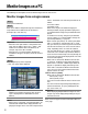
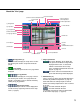

Table Of Contents
- Preface
- Monitor Images on a PC
- Action at an Alarm Occurrence
- About the image recognition function
- Transmit Images onto an FTP Server
- About the Network Security of This Unit
- Display the Setup Menu and Configure the Settings of the Unit using a PC
- How to display the setup menu
- How to operate the setup menu
- Configure the basic settings of the unit [Basic setup]
- Configure the settings relating to images and audio [Camera setup]
- Configures the multi-screen settings [Multi-screen setup]
- Configure the AVMD settings [Video analytics setup]
- Configure the alarm settings [Alarm setup]
- Configure the settings relating to the authentication [Authentication setup]
- Configure the settings of the servers [Server setup]
- Configuring the network settings [Network setup]
- Maintenance of the unit [Maintenance]
- About the Displayed System Log
- Troubleshooting

5
About the "Live" page
q [Setup] button (*1)
Click this button to display the setup menu. The but-
ton will turn green and the setup menu will be dis-
played.
w [Live] button
The button will turn green and the "Live" page will be
displayed.
e [1] to [4] buttons
Click this button to display the "Live" page. The but-
ton will turn green and the "Live" page will be dis-
played. It is possible to select a desired channel by
clicking the [1] to [4] buttons.
r Multi-screen buttons
Images from multiple cameras can be displayed on
a multi-screen by registering cameras on the setup
menu. (☞ page 8)
t Image type buttons
: The letters "MPEG-4" on the button will
turn green and an MPEG-4 image will be
displayed. When "OFF" is selected for
"MPEG-4 transmission" on the setup
menu, the [MPEG-4] button will not be dis-
played. (☞ page 27)
: The letters "JPEG" on the button will turn
green and JPEG image will be displayed.
y AUX buttons (*2)
Select 1 (AUX1) to (AUX3) from the pull-down menu
and click the [OPEN/CLOSE] button. (☞ page 43)
AUX1 and AUX2 are auxiliary outputs of camera.
AUX3 is the auxiliary output from the AUX 1 terminal
of this unit.
: The AUX connector will open.
: The AUX connector will close.
It is possible to change the names of AUX buttons
on the "Alarm setup" page. (☞ page 43)
w [Live] button
e [1] to [4] buttons
q [Setup] button
y AUX buttons
r Multi-screen buttons
t Image type buttons
i ZOOM buttons
o FOCUS buttons
!0 AUTO MODE !1 Control pad/buttons
!2 BRIGHTNESS buttons
!3 Preset
!6 Unit title
!8 Alarm occurrence indication button
@0 One shot button
!9 Full screen button
@2 Audio output button
@1 Mic input button
@4 Main area
!5 Track
!4 Frame
u B/W button
@3 Time and date
!7 Camera title