ENGLISH DEUTSCH ESPAÑOL WV-CF250 WV-CF254 FRANÇAIS Colour CCTV Camera Before attempting to connect or operate this product, please read these instructions completely
ENGLISH VERSION CAUTION RISK OF ELECTRIC SHOCK DO NOT OPEN CAUTION: TO REDUCE THE RISK OF ELECTRIC SHOCK, DO NOT REMOVE COVER (OR BACK), NO USER SERVICEABLE PARTS INSIDE. REFER SERVICING TO QUALIFIED SERVICE PERSONNEL. The lightning flash with arrowhead symbol, within an equilateral triangle, is interned to alert the user to the presence of uninsulated "dangerous voltage" within the product's enclosure that may be of sufficient magnitude to constitute a risk of electric shock to persons.
PREFACE ............................................................................................................................................................ 2 FEATURES .......................................................................................................................................................... 2 PRECAUTIONS ...................................................................................................................................................
PREFACE PRECAUTIONS Panasonic's WV-CF250 series colour digital camera introduces a new level of high picture quality and high resolution through the use of a 1/3-inch interline transfer CCD image sensor having 753 horizontal pixels (picture elements), and digital signal processing LSIs. This model offers cutting-edge technology for advanced video surveillance. 1. Do not attempt to disassemble the camera. To prevent electric shock, do not remove screws or covers.
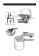
MAJOR OPERATING CONTROLS AND THEIR FUNCTIONS OP EN LO CK UP LEFT RIGHT SET DOWN CK LO EN OP -3-
q Panning Table This adjusts the panning angle of the camera. o w Camera Head This adjusts the tilting angle of the camera. !0 Lens Holders These holders bring the picture in an upright position on the monitor screen. e Focus Ring This adjusts the focus. !1 Dome Cover This protects the camera head. r Zoom Ring This adjusts the angle of view. t (D) (Down Button) This button moves the cursor downward. It also selects items in the CAM SET UP menu.
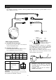
CONNECTION Precaution: The following connections should be made by qualified service personnel or system installers in accordance with the local codes. 220-240V AC (WV-CF250) 24V AC (WV-CF254) Coaxial Cable Video Output Cable BNC Plug OP EN LO CK To Video IN (CAMERA IN) BNC Plug Approx. 3 mm (1/8 inch) Up Contact • Power supply connection A. WV-CF250 (220-240V AC 50Hz) Connect the AC power cable to an electrical outlet of 220-240V AC 50Hz. Recommended wire gauge sizes for 24 V AC line.
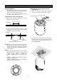
INSTALLATION 2. Mounting the camera onto the camera fixing bracket Important Notices: • The following installation should be made by qualified service personnel or system installers and should confirm to all local codes. • Be sure to use a ceiling board having enough strength to support this camera. 2-1. Make sure the video output cable and power cable are fixed by the coaxial cable clamps. Video output cable Coaxial cable clamps 1. Mounting the camera fixing bracket 1-1.
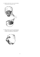
2-3. Remove the dome cover from the camera by turning it counterclockwise. 2-5. Turn the camera in the LOCK direction until the lock tab of the camera fixing bracket meets the lock line of the camera. Lock tab Lock line OP EN LO CK OPEN OPEN LOCK LOCK 2-6. Attach the fall prevention cap on the lock tab of the camera fixing bracket as shown below to prevent the camera from falling down. OP EN LO CK 2-4.
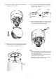
2-7. Match the four grooves on the camera with the four projections on the dome cover. OP EN LO CK Grooves Projections 2-8. Attach the dome cover to the camera by turning this cover clockwise so that the window in the dome cover matches the camera head.
ADJUSTMENT 1. Panning 3. Uprighting the picture Loosen the 2 lens holders and bring the picture in an upright position on the monitor screen by turning the camera head. The Panning table can be moved between the guide lines. Guide lines OP EN LO CK SUPE RD YN AM IC Lens holders Panning table 4. Focusing 2. Tilting the camera Precaution: The focus adjustment should be done at the same time as the camera angle adjustment. The tilting angle is shown below.
4-5. Set the correct focus by turning the focus ring. 4-6. After setting the correct focus, tighten the focus lock lever. 4-7. After adjusting the angular field of view and focus, attach the dome cover to the camera body.
SYSTEM CONNECTION Shown below is an example of a basic system connection.
SETUP 1. CAMERA SETUP MENU This camera utilizes a user setup menu that is displayed on-screen. The setup menu contains various items that form a tree-type structure as shown below. It is described in the following section : “2. SETUP OPERATION.
White Balance ATW Special menu AWC Manual Level Adjustment Manual Level Adjustment Manual Mask Area Selection Manual Mask Area Selection Chroma Gain AP Gain Pedestal • Opening the Setup Menu ** CAM SET UP ** CAMERA ID OFF ALC/ELC ALC SHUTTER --AGC ON SYNC INT WHITE BAL ATW (S) for a second or longer.
↵ ↵ ↵↵ ** CAM SET UP ** CAMERA ID OFF ALC/ELC ALC SHUTTER --AGC ON SYNC INT WHITE BAL ATW ↵↵ ** CAM SET UP ** CAMERA ID OFF ALC/ELC ALC SHUTTER --AGC ON SYNC INT WHITE BAL ATW END SET UP DISABLE END SET UP ENABLE • Editing the SPECIAL menu To edit the SPECIAL menu (change settings), proceed as for editing the CAM SET UP menu above. Move the cursor to END after the words SET UP ENABLE appear. Then press (L) and (R) simultaneously for 2 seconds or longer. The SPECIAL menu appears on the monitor.
SETTING PROCEDURES To erase all characters in the editing area Move the cursor to RESET and press (S). All characters in the editing area disappear. 1. Camera Identification (CAMERA ID) Setting You can use the camera identification (CAMERA ID) to assign a name to the camera. The camera ID consists of up to 16 alphanumeric characters. You can select whether to have the camera ID displayed on the monitor screen or not. To determine the display position of the CAMERA ID 1.
2-1. ALC Mode with SUPER-D ON 2-2. ALC Mode with SUPER-D OFF and ELC Mode Super Dynamic Function (SUPER-D) The important object in a scene is usually placed in the centre of the monitor’s screen. In SUPER-D mode, more photometric weight is given to the centre of the screen (where the important object is located) than to the edge of the picture (where a bright backlight would most likely be located). You can use the SUPER-D function if you select ALC.
4. Repeat step 3 to mask the desired areas. To cancel masking, move the cursor to that area and press (S). 4. Gain Control Setting (AGC ON/OFF) You can set the gain (brightness level portion of an image) to automatic level adjustment (ON) or fixed level (OFF). Turns to white ** CAM SET UP ** CAMERA ID OFF ALC/ELC ALC SHUTTER --AGC ON SYNC INT WHITE BAL ATW ↵ ↵↵ Blinking END 5. After masking is completed, press (S) for 2 seconds or longer. The ALC CONT menu appears. 6.
5-1. Line-lock Sync Mode (LL) 8. Press (L) or (R) to match the vertical phase for both video output signals as closely as possible. (FINE adjustment can be made up to 22.5 degrees by pressing (L) or (R).) Notes: • When the “I” cursor reaches the “+” end, it jumps back to “−”. At the same time, COARSE is incremented by one step to enable a continuous adjustment. The reverse takes place when the “I” cursor reaches the “−” end.
• AWC (Automatic White Balance Control) In this mode, accurate white balance is obtained within a colour temperature range of approximately 2 300-10 000K. 1. Move the cursor to the WHITE BAL parameter and select AWC → PUSH SW. 5. Press (L) or (R) to obtain the optimum amount of blue gain. Note: When you need to set MASK SET, re-adjust to obtain the optimum amount of red and blue gain. 7.
To close the SPECIAL menu and return to the CAM SET UP menu Move the cursor to RET and press (S). To close the SPECIAL menu and return to the camera picture Move the cursor to END and press (S). PREVENTION OF BLOOMING AND SMEAR When the camera is aimed at a bright light, such as a spotlight, or a surface that reflects bright light, smear or blooming may appear. Therefore, the camera should be operated carefully in the vicinity of extremely bright objects to avoid smear or blooming.
SPECIFICATIONS Pick-up Device: Scanning Area: Scanning: Horizontal: Vertical: Synchronization: Video Output: Horizontal Resolution: Signal-to-Noise Ratio: Dynamic Range: Minimum Illumination: Angular Field of View: Gain Control: White Balance: Aperture: Electronic Light Control: Super-D: Electronic Shutter Speed: Ambient Operating Temperature: Ambient Operating Humidity: Power Source: Dimensions: Weights: 753 (H) x 582 (V) pixels, Interline Transfer CCD 4.9 (H) x 3.
Matsushita Electric Industrial Co., Ltd. Central P.O.