
Operating instructions


-5-
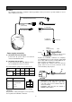
CONNECTION
Precaution:
The following connections should be made by qualified service personnel or system installers in accor-
dance with the local codes.
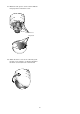
OPEN
LOCK
To Video IN
(CAMERA IN)
Video Output Cable
24V AC
(WV-CF254)
BNC Plug
BNC
Plug
Coaxial Cable
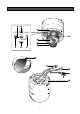
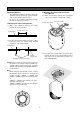
How to assemble the cable with the accessory
connector
Strip back the cable jacket approx. 3 mm (1/8 inch)
and separate the individual conductors.
Recommended wire gauge sizes for 24 V AC line.
#24
(0.22mm
2
)
Copper wire size
(AWG)
Length
of Cable
(Approx.)
(m)
(ft)
#22
(0.33mm
2
)
#20
(0.52mm
2
)
#18
(0.83mm
2
)
20 30 45 75
65 100 160 260
Accessory Connector Information
Pin No. Power Source
1 :
2 :
3 :
4 :
24 V AC LIVE
24 V AC NEUTRAL
Ground
Not used
Prepare the individual conductors for clamping.
Use MOLEX band tool part number 57027-5000
(for UL-Style Cable UL1015) or 57026-5000 (for UL-
Style UL-1007) for clamping the contacts.
After clamping the contacts, push them into the
proper holes in the accessory connector of this
camera until they snap in place.
Shrinking the cable-entry seal is a one-time
procedure. Do not shrink the cable-entry
seal until it has been ascertained that the
unit is functioning.
CONNECT THIS TO 24V AC CLASS 2
POWER SUPPLY ONLY.
A
Up
Wire
Contact
Up
Contact
Wire
Approx.
3 mm (1/8 inch)
Insert the wire until A position
and clamp the contacts.
1
3
2
4
• Power supply connection
A. WV-CF250 (220-240V AC 50Hz)
Connect the AC power cable to an electrical
outlet of 220-240V AC 50Hz.
B. WV-CF254 (24V AC 50Hz)
Connect the power cable with MOLEX connec-
tor according to the references below.
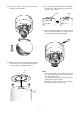
CAUTION
220-240V AC (WV-CF250)
Insert